Mazda 6. Manual - part 203
ON-BOARD DIAGNOSTIC
K–53
K
9. Drive the vehicle in D range and shift gears between 1st and 4th (TCC operation) gear.
10. Gradually slow down and stop the vehicle.
11. Make sure that the repaired DTC does not recur.
End Of Sie
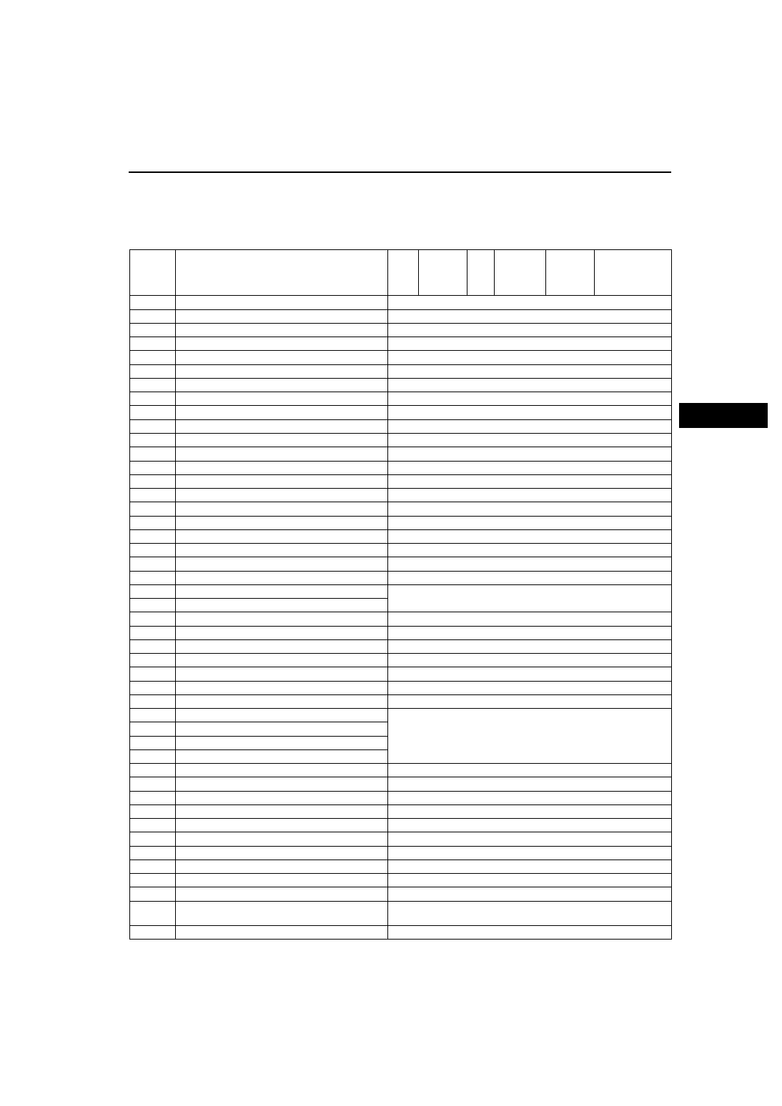
DTC TABLE
A6E567001030W04
DTC No.
Condition
MIL
HOLD
indicator
light
flashes
DC
Monitor
item
Memory
function
Page
P0010
CMP actuator circuit malfunction
(See
P0011
CMP timing over advanced
P0012
CMP timing over retarded
P0031
Front HO2S heater circuit low
(See
P0032
Front HO2S heater circuit high
P0037
Rear HO2S heater circuit low
(See
P0038
Rear HO2S heater circuit high
P0101
MAF sensor inconsistent with TP sensor
(See
P0102
MAF circuit low input
(See
P0103
MAF circuit high input
(See
P0107
MAP sensor circuit low input
(See
P0108
MAP sensor circuit high input
(See
P0111
IAT circuit performance problem
(See
P0112
IAT circuit low input
P0113
IAT circuit high input
(See
P0117
ECT circuit low input
(See
P0118
ECT circuit high input
(See
P0121
Throttle position stuck close
(See
P0122
TP circuit low input
(See
P0123
TP circuit high input
(See
P0125
Excessive time to enter closed loop fuel control
(See
P0131
Front HO2S no inversion (low stuck)
P0132
Front HO2S no inversion (high stuck)
P0133
Front HO2S circuit malfunction
(See
P0134
Front HO2S circuit no activity detected
P0138
Rear HO2S circuit high input
P0140
Rear HO2S circuit no activity detected
(See
P0171
Fuel trim system too lean
P0172
Fuel trim system too rich
(See
P0300
Random misfire detected
(See
P0301
Cylinder No.1 misfire detected
P0302
Cylinder No.2 misfire detected
P0303
Cylinder No.3 misfire detected
P0304
Cylinder No.4 misfire detected
P0327
Knock sensor circuit low input
(See
P0328
Knock sensor circuit high input
(See
P0335
CKP sensor circuit malfunction
(See
P0340
CMP sensor circuit malfunction
(See
P0351
Ignition coil (No.1, No.4) circuit malfunction
P0352
Ignition coil (No.2, No.3) circuit malfunction
P0401
EGR flow insufficient detected
P0402
EGR flow excessive detected
P0403
EGR valve motor coils open or short
(See
P0420
Catalyst system efficiency below threshold
P0443
Evaporative emission control system purge
control valve circuit malfunction
P0480
Fan control module circuit malfunction
(See