Mazda 6. Manual - part 155
F–142
ON-BOARD DIAGNOSTIC
DTC P0500
A6E397001087W01
Diagnostic procedure
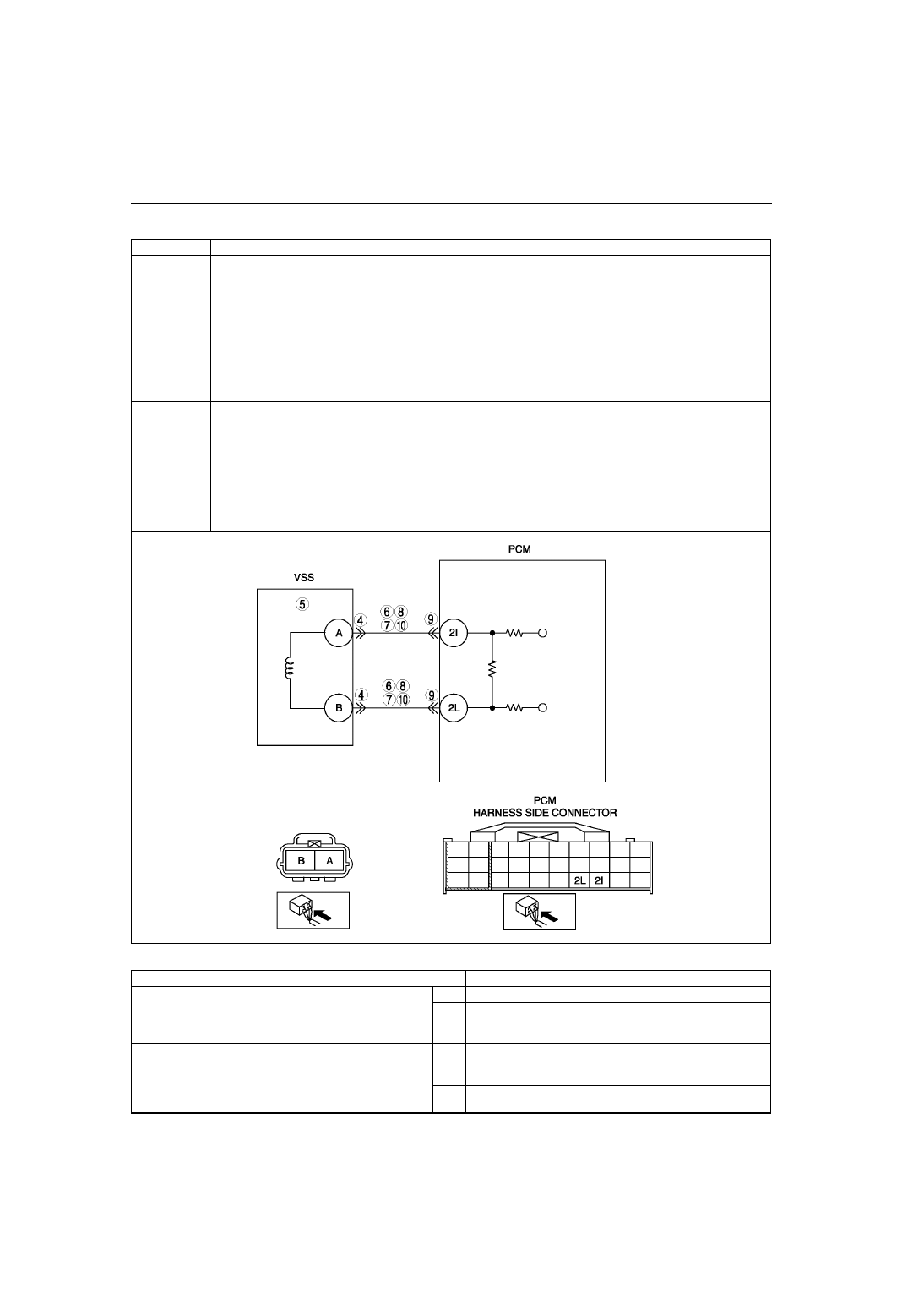
DTC P0500
Vehicle speed sensor (VSS) circuit malfunction (MTX vehicles without ABS)
DETECTION
CONDITION
• Vehicle speed signal does not input after following conditions are met:
— Gear is in other than neutral position
— Load is above 40%
— Engine speed is 2,000 rpm or above
Diagnostic support note:
• This is a continuous monitor (CCM).
• MIL illuminates if PCM detects the above malfunction conditions in two consecutive drive cycles or in one
drive cycle while the DTC for the same malfunction has been stored in the PCM.
• PENDING CODE is available if PCM detects the above malfunction condition during first drive cycle.
• FREEZE FRAME DATA is available.
• DTC is stored in PCM memory.
POSSIBLE
CAUSE
• VSS malfunction
• ABS/TCS/DCS malfunction
• Connector or terminal malfunction
• Open circuit between PCM terminal 2I and VSS terminal A
• Open circuit between PCM terminal 2L and VSS terminal B
• Short to ground between PCM terminal 2I and VSS terminal A
• Short to ground between PCM terminal 2L and VSS terminal B
• Short to power between PCM terminal 2I and VSS terminal A
• Short to power between PCM terminal 2L and VSS terminal B
• PCM malfunction
STEP
INSPECTION
ACTION
1
VERIFY FREEZE FRAME DATA HAS BEEN
RECORDED
• Has FREEZE FRAME PID DATA been
recorded?
Yes Go to next step.
No
Record FREEZE FRAME PID DATA on repair order, then
go to next step.
2
VERIFY RELATED SERVICE INFORMATION
AVAILABILITY
• Check for related Service Information
availability.
• Is any related Service Information available?
Yes Perform repair or diagnosis according to available Service
Information.
• If vehicle is not repaired, go to next step.
No
Go to next step.