Mazda 6. Manual - part 98
ELECTRICAL SYSTEM
GI–23
GI
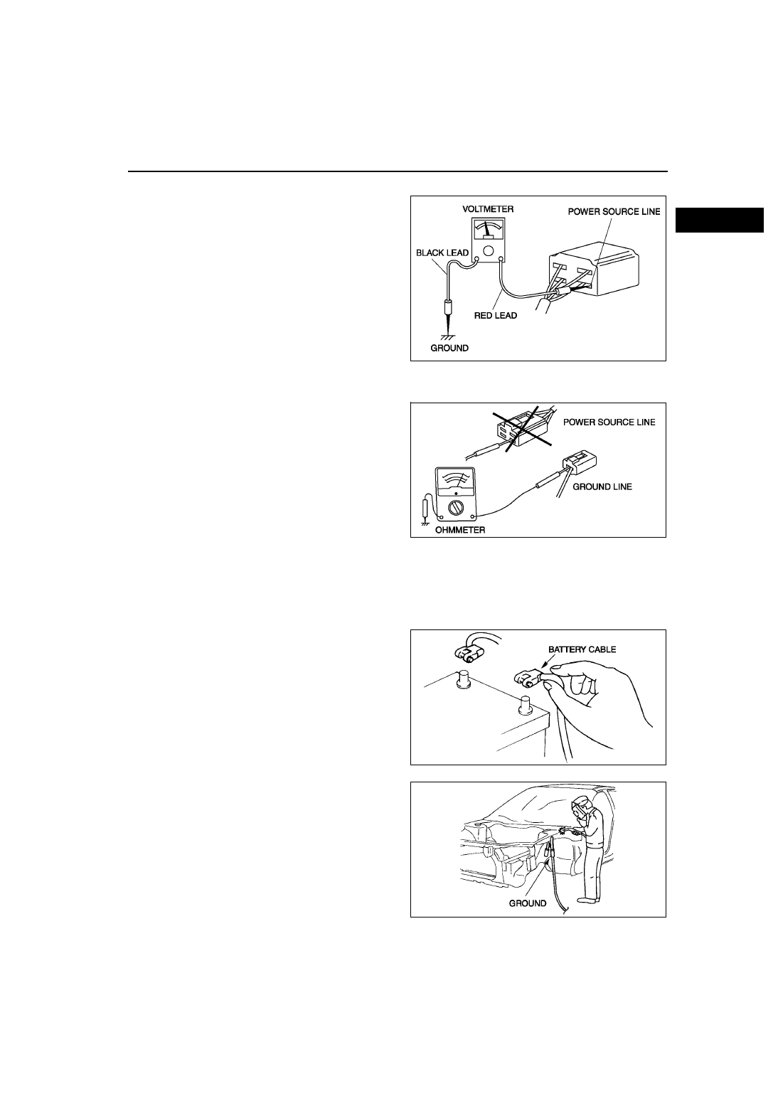
Voltmeter
• The DC voltmeter is used to measure circuit
voltage. A voltmeter with a range of 15 V or more
is used by connecting the positive (+) probe (red
lead wire) to the point where voltage will be
measured and the negative (-) probe (black lead
wire) to a body ground.
Ohmmeter
• The ohmmeter is used to measure the resistance
between two points in a circuit and to inspect for
continuity and short circuits.
Caution
• Do not connect the ohmmeter to any
circuit where voltage is applied. This will
damage the ohmmeter.
End Of Sie
PRECAUTIONS BEFORE WELDING
A6E201700006W04
Vehicles have various electrical parts. To protect the parts from excessive current generated when welding, be
sure to perform the following procedure.
1. Turn the ignition switch to the LOCK position.
2. Disconnect the battery cables.
3. Securely connect the welding machine to the
ground near the welding area.
4. Cover the peripheral parts of the welding area to
protect them from weld spatter.
End Of Sie
X3U000WBC
YMU000WAL
WGIWXX0007E
WGIWXX0008E