Mazda 6. Manual - part 97


  Index      Mazda     Mazda 6 - service repair manual 2002 year


Search            


Content   ..  95  96  97  98   ..


Mazda 6. Manual - part 97


ELECTRICAL SYSTEM 

GI–19

GI

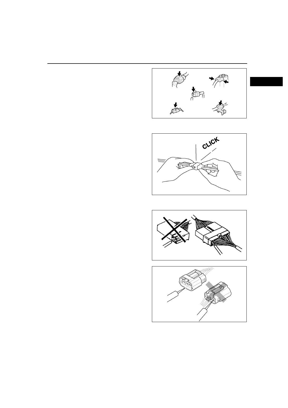
• Connectors can be disconnected by pressing or 

pulling the lock lever as shown.

Locking connector

• When locking connectors, listen for a click 

indicating they are securely locked.

Inspection

• When a tester is used to inspect for continuity or 

measuring voltage, insert the tester probe from 
the wiring harness side.

• Inspect the terminals of waterproof connectors 

from the connector side since they cannot be 
accessed from the wiring harness side.

Caution

• To prevent damage to the terminal, wrap 

a thin wire around the tester probe before 
inserting into terminal.

WGIWXX0042E

X3U000WB1

X3U000WB2

WGIWXX0045E

GI–20

ELECTRICAL SYSTEM 

Terminals
Inspection

• Pull lightly on individual wires to verify that they 

are secured in the terminal.

Replacement

• Use the appropriate tools to remove a terminal as 

shown. When installing a terminal, be sure to 
insert it until it locks securely.

• Insert a thin piece of metal from the terminal side 

of the connector and with the terminal locking tab 
pressed down, pull the terminal out from the 
connector.

Sensors, Switches, and Relays

• Handle sensors, switches, and relays carefully. 

Do not drop them or strike them against other 
objects.

Wiring Harness
Wiring color codes

• Two-color wires are indicated by a two-color code symbol.

• The first letter indicates the base color of the wire and the second the color of the stripe.

X3U000WB4

X3U000WB5

X3U000WB6

CODE

COLOR

CODE

COLOR

B

Black

O

Orange

BR

Brown

P

Pink

G

Green

R

Red

GY

Gray

V

Violet

L

Blue

W

White

LB

Light Blue

Y

Yellow

LG

Light Green

X3U000WB7

ELECTRICAL SYSTEM 

GI–21

GI

Fuse
Replacement

• When replacing a fuse, be sure to replace it with 

one of the same capacity. If a fuse fails again, the 
circuit probably has a short and the wiring should 
be inspected.

• Be sure the negative battery terminal is 

disconnected before replacing a main fuse.

• When replacing a pullout fuse, use the fuse 

puller.

Direction of View for Connector
Part-side connector
Direction of view is from the terminal side.
*

:  Part names are shown only when there are 

multiple connector drawings.

YMU000WA1

YMU000WAK

WGIWXX0100E

GI–22

ELECTRICAL SYSTEM 

Vehicle-harness-side connector
Direction of view is from the harness side.
*

:  Part names are shown only when there are 

multiple connector drawings.

Other
Because vehicle-harness-side connectors, such as 
the DLC 2, have to be viewed from the terminal side, 
the direction of view is from the terminal side.

End Of Sie

ELECTRICAL TROUBLESHOOTING TOOLS

A6E201700006W03

Jumper wire

• A jumper wire is used to create a temporary 

circuit. Connect the jumper wire between the 
terminals of a circuit to bypass a switch.

Caution

• Do not connect a jumper wire from the 

power source line to a body ground. This 
may cause burning or other damage to 
wiring harnesses or electronic 
components.

WGIWXX0101E

WGIWXX0102E

X3U000WBB


Content   ..  95  96  97  98   ..