Iveco Stralis AT/AD. Manual - part 306
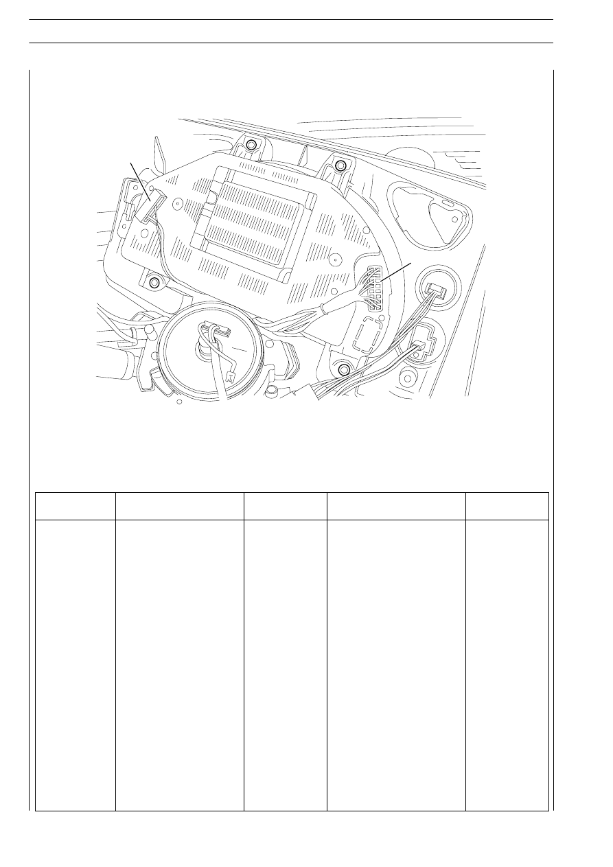
B
A
49837
III.8
ELECTRONIC SYSTEMS
S
TRALIS
AT/AD
Base - January 2003
Ref.
A - Black
Component
code
B - Blue
Component
code
1
Link K - Diagnosis
72021
-
-
2
-
-
-
-
3
CAN H (VDB) Line
-
-
-
4
CAN L (VDB) Line
-
-
-
5
-
-
-
-
6
-
-
-
-
7
-
-
-
-
8
Predisposition
ST14
-
-
9
Tachograph speed signal
72021
-
-
10
CAN H (ICB) Line
-
-
-
11
CAN L (ICB) Line
-
EDC signal input
8515D
12
-
-
-
-
13
CAN H (IDB) Line
-
-
-
14
CAN L (IDB) Line
-
-
-
15
-
-
-
-
16
Rev counter signal
40011
-
-
17
Rev counter signal
40011
-
-
18
Speed signal (intarder)
ST25
Power from fuse
70601
19
-
-
Mass
-
20
Predisposition
ST14
Power from fuse
70601