Iveco Stralis AT/AD. Manual - part 233
12
STEERING
S
TRALIS
AT/AD
Base - January 2003
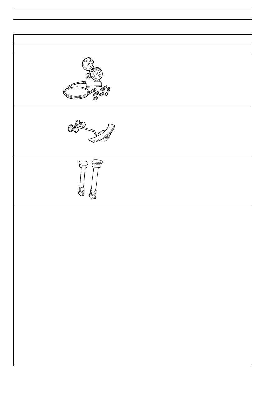
TOOL NO.
DESCRIPTION
99374393
Tool with pressure gauges for checking the power steering hydraulic
pressure
99374398
Graduated sector and scale steering wheel play control (to be used
with 99374393)
99374399
Couple of expanders for locking the wheels (to be used with
99374393-99374398)