Iveco Stralis AT/AD. Manual - part 125


  Index      Iveco     Iveco Stralis AT/AD - service repair manual 2003 year


Search            


Content   ..  123  124  125  126   ..


Iveco Stralis AT/AD. Manual - part 125


40787

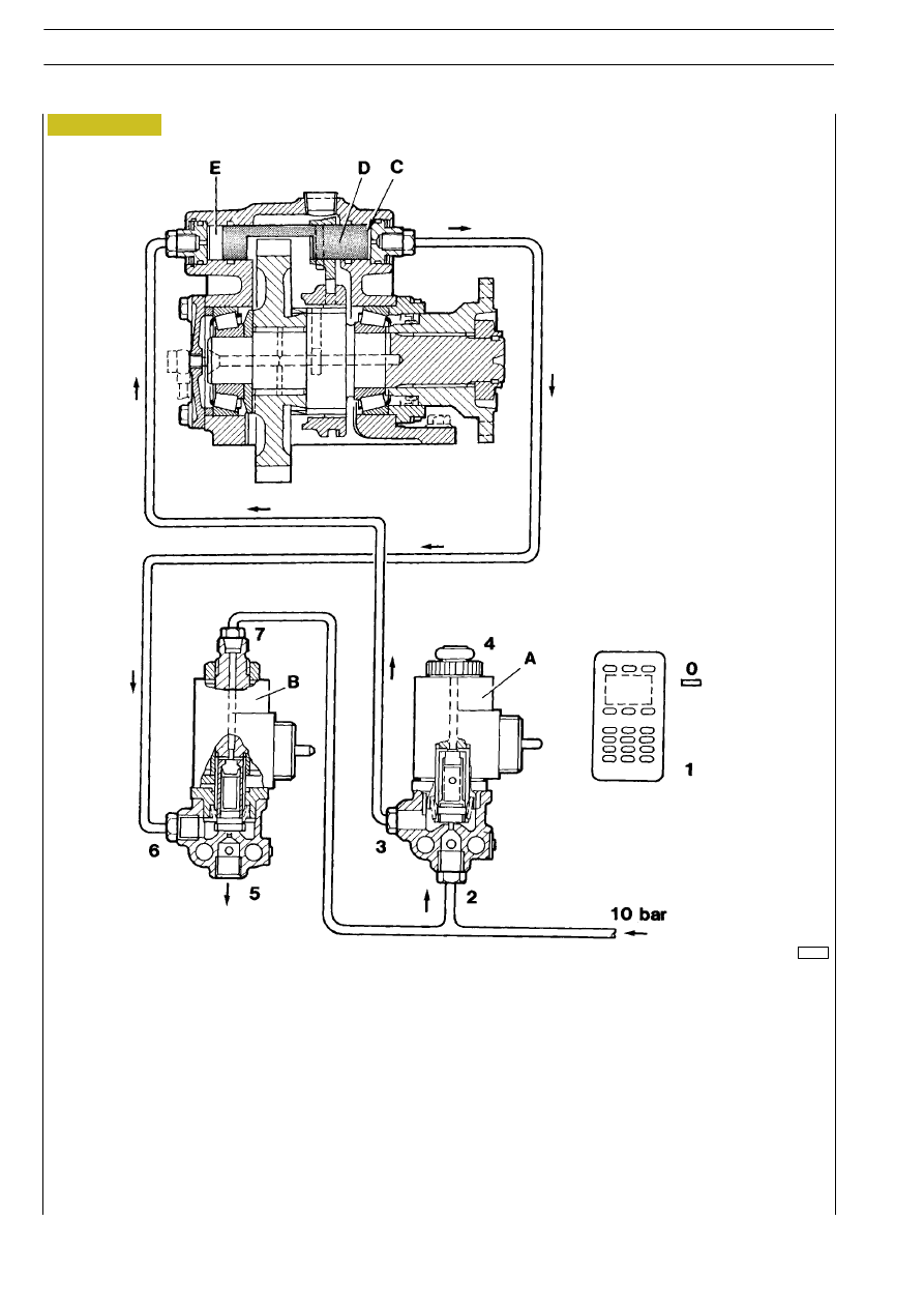
Operation (power take off disengaged)

A = Electro-pneumatic valve N.A. (usually open) with switch disengaged
B = Electro-pneumatic valve N.C. (usually closed) with switch disengaged

With the switch in position 0 (disengaged) the electromagnets of the valves A - B are disconnected and therefore the circuit of the
valve A remains open and that of valve B remains closed.
The air taken in enters valve A by link (2), leaves by link (3) and passes through the pipes to chamber E, moving the control rod
with fork D in power take off position disengaged.
At the same time the air in chamber C passes through the piping to the link (6) and passes into the air by link (5).

Figure 5

242

POWER TAKE OFF

S

TRALIS

AT/AD

Base - January 2003

40787

Operation (power take off engaged)

A = Electro-pneumatic valve N.A. (usually closed) with switch disengaged
B = Electro-pneumatic valve N.C. (usually open) with switch disengaged

With the switch in position 1 (engaged) the electromagnets of the valves A - B are excited and therefore the circuit of the valve
A open and open that of valve B.
The air taken in through link (7)enters valve B leaves by link (6) and passes through the pipes to chamber C, moving the control
rod with fork D in power take off position engaged.
At the same time the air in chamber E passes through the piping to the link (3) into valve A and passes into the air by link (4).

Figure 6

POWER TAKE OFF

243

S

TRALIS

AT/AD

41019

Figure 7

Removal

This operation comprises:
- Removing - refitting propeller shafts (see relevant section

505620).

- Removing - refitting gearbox (see relevant section

530210).

- Removing - refitting clutch (see relevant section 505210).
Take out the plug (1) and drain off the oil into a container.
Loosen the nut (13) fixing the drive output flange (12).
Take out the screws (11) and detach the bottom cover (10)
together with the oil pump (17) and oil filter (18).
Disconnect the electrical connections and the oil and air pipes
from the drive (5).
Take out the screws (14) and disconnect the drive (1) from
the box (1).
Take out the screws (15) and take off the flywheel (16) for
the clutch coupling.
Take out the screws (6) and disconnect the laminar coupling
(8) from the engine flywheel (7).
Remove the nuts for fixing the power take-off assembly and
detach it from the engine.

Refitting

Provisionally mount the bottom cover (10). Screw down the
screw (2) without the washer (3) in contact with the driven gear
(4). Using a feeler gauge, measure the distance between the
underside of the head of the screw (2) and the box (1), distance
A.

Take out the screw (2), apply LOCTITE 242E on its thread and
screw it back on, placing a washer in between with a thickness
of:

S = A + B

where A is the distance measured

B = 0,3

± 0,1

corresponding to the distance between the end of the screw (2)
and the driven gear (4).
Tighten the screw (2) to the required torque.

!

Screw (2) has a left-hand thread.

Take the bottom cover (10) back off. Refit the power take-off
assembly by carrying out the steps described for removal in
reverse order and observing the following:
- Lubricate the shaft (9) with MOLYCATE HSC grease.
- Apply LOCTITE 510 on the mating surfaces of the drive

(5) and bottom cover (10).

- Apply LOCTITE 242E on the thread of the screws or

plugs in contact with the oil.

- Tighten the screws/nuts to the required torque.
- The nut (13) fixing the drive output flange has to be

tightened to a torque of 465 Nm (46.5 kgm) after
mounting the drive assembly (5).

- Replenish the assembly with lubricating oil of the required

grade and quantity.

244

POWER TAKE OFF

S

TRALIS

AT/AD

Base - January 2003

REMOVING - REFITTING TOTAL POWER TAKE-OFF ASSEMBLY

41019

41020

41021

Figure 8

Figure 9

Figure 10

Position the whole assembly on the rotary stand 99322205.
Lock the rotation of the laminar coupling (2) with the reaction
lever 99370317 (1) and using a suitable wrench unscrew the
retaining screws (3). Remove the laminar coupling and the
flange.

Using the eyebolt 993605003 (1) and lift, remove the shaft with
the gear wheel (2).

Unscrew the screws (1), take off the cover (2) together with the
seal and recover the adjustment ring (3).

41022

41024

41023

Figure 11

Figure 12

Figure 13

Using an appropriate drift, drive out the shaft (2) and extract
the middle gear (1). Take the seal out of the box.

Using suitable pliers (1), remove the split ring (2).

Extract the ball bearing (4) with the extractor 99341003 (1),
grips 99341009 (2) and reaction block 99345049 (3).

Removing bearing for shaft with gear wheel

534510

Removing drive assembly

OVERHAULING
Removing main box

POWER TAKE OFF

245

S

TRALIS

AT/AD


Content   ..  123  124  125  126   ..