Iveco Stralis AT/AD. Manual - part 107
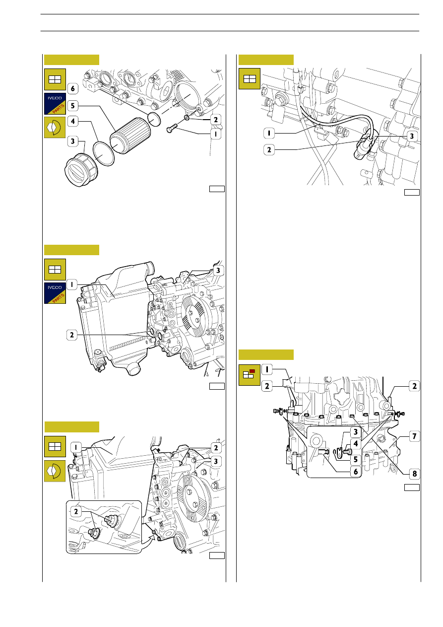
Figure 17
Figure 18
Figure 19
Figure 20
Figure 21
Position the magnet (6) on the filter (5) and insert this into
the hydraulic retarder. Fit the plug (3) with a new seal (4).
Screw down the fastening screw (1) with the washer (2).
Fit two new seals (2) on the hydraulic retarder (3) and mount
the heat exchanger (1) (if applicable).
Screw down the four nuts (2) fixing the heat exchanger (1) to
the hydraulic retarder (3) and tighten them to the prescribed
torque.
Connect the electric wiring (1) to the speed sensor (3) and
tighten the ring nut (2).
Replenish the gearbox with the prescribed grade and
quantity of lubricating oil.
Removing the rear box
Disconnect the gear actuator, as described in the respective
chapter.
Remove the hydraulic retarder as described under the
relevant heading.
Remove the screws (4) fixing the plates (3) fastening the pins
(6) and extract these together with the seals (5) from the
central box (7).
Extract the two centring pins (2) and remove the screws (8)
of fixing rear box (1).
70936
70933
70955
70937
70934
GEARBOX EuroTronic 12 AS 2301 D.D./O.D. with Intarder
165
S
TRALIS
AT/AD