Iveco Stralis AT/AD. Manual - part 99


  Index      Iveco     Iveco Stralis AT/AD - service repair manual 2003 year


Search            


Content   ..  97  98  99  100   ..


Iveco Stralis AT/AD. Manual - part 99


45954

70848

70849

70850

Figure 33

Figure 34

Figure 35

Figure 36

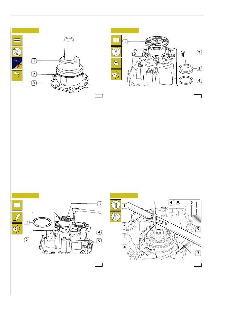
Using the driver 99374221 (1), fit the seal (2) in the cover (3).

Mount the adjustment ring (1), of the thickness determined in
the preceding measurement, on the bearing (2, Figure 31) of
the spider shaft (3).

Spread IVECO sealant 1905685 on the mating surface of the
cover (4) with the box (5) and fit it onto the box, tightening
the screws (2) to the prescribed torque.

Heat the sleeve (1) to 90

°C and fit it onto the spider shaft (1).

Fit on a new seal (4), the disc (3) and screws (2) and tighten
them to the prescribed torque.

Adjusting main shaft end float

Position two calibrated blocks (2) on the rear box (4). Place
a calibrated rule (1) on them and, using a depth gauge (3),
measure the distance between the top side of the rule and the
end of the spider shaft (5), distance A.

132

GEARBOX EuroTronic 12 AS 2301 D.D./O.D.

S

TRALIS

AT/AD

Base - January 2003

70851

70852

Figure 37

Figure 38

Fit the connecting sleeve (7) together with the circlip (5) on
the main shaft (6).

Position two calibrated blocks (2) on the middle box (4) and
place a calibrated rule (1) on them.

!

The calibrated blocks and rule must be the same ones
used in the preceding measurement.

Using a depth gauge (3), measure the distance between the
top end of the circlip (5) and the top side of the calibrated rule
(1), distance B.

The thickness S of the main shaft end float adjustment ring is
determined by the following equation:

S = (A - B) - 2

For your information (see Figure 39), subtracting the thickness
of the calibrated blocks and rule:

- from the distance A gives the distance X corresponding

to the distance between the end of the spider shaft (2)
from the mating surface of the rear box (1).

- from the distance B gives the distance Y corresponding

to the distance between the circlip (4) and the mating
surface of the middle box (3).

GEARBOX EuroTronic 12 AS 2301 D.D./O.D.

133

S

TRALIS

AT/AD

Position the adjustment ring (2) (of the thickness determined
in the preceding measurements) on the main shaft (5). Mount
the connecting sleeve (1) and the tube (4).

Mount the plate (6) together with the coupling body (3).

70853

70854

70855

70856

70857

Figure 39

Figure 40

Figure 41

Figure 42

Figure 43

Synchronizing device assembly for engaging
normal or reduced gears
Removal

1. Synchronizing device assembly - 2. Synchronizing device

ring - 3. Sliding sleeve - 4. Pawl - 5. Spring -

6. Synchronizing device ring.

Put a cloth on the synchronizing device assembly (1) so that,
when dismantling it, the springs (5) and pawls (4) are held back
as they come out of their seats.

Put the springs (2) and pawls (3) into the seats of the
synchronizing device rings (1) and fasten them with the tools
99370172 (4).

Position the synchronizing device ring (2) on the synchronizing
device ring (3) so that it is possible to fit the sliding sleeve (1)
onto them. On completing assembly, remove the tools
99370172 (4).

Fit the synchronizing device assembly (1) on the coupling body
(3, Figure 39) with the ring groove (

→) facing downwards.

134

GEARBOX EuroTronic 12 AS 2301 D.D./O.D.

S

TRALIS

AT/AD

Base - January 2003

70858

70860

70859

70831

70862

Figure 44

Figure 45

Figure 46

Figure 47

Figure 48

Position the fork (1) with the plugs (3) and the reliefs (') facing
as illustrated in the figure.

Fit on the rod (4) and connect it to the fork (1). Fit on the oil
pipe (2).

Take out the screws (1) and remove the cover (2) with its seal
(3). Remove the screw (4) with the washer (5).

Spread IVECO sealant 1905685 onto the mating surface of
the middle box (6). Fit the eyebolts 99368811 (1) to the
sleeve (2). Using ropes and a lifter, position the rear box (4)
coaxially to the middle one (6).

Screw down the screws (6) without tightening them; insert the
centring pins (5) and tighten the screws (6) to the prescribed
torque.
Fit the fork joint pins (4) with fresh seals (3) and tighten the
screws (1) fixing the fastening plates (2) to the prescribed
torque.

Fit: the screw (4) with a new washer (5) and tighten it to the
prescribed torque.

Fit the cover (2) with a fresh seal (3) and tighten the fixing
screws (1) to the prescribed torque.

Block rotation of the sleeve (7) by applying the lever
99370317 (8) and tighten the fixing screws (6) to the
prescribed torque.

Insert the rod (3) of appropriate diameter in the hole for the
screw (4, Figure 45) and in the oil pipe (5) to guide this into
its seat, while lowering the rear box (4). Lower the rear box
(4), paying attention that the spider shaft, oil pipe (5) and rod
(7) go into their seat correctly.

GEARBOX EuroTronic 12 AS 2301 D.D./O.D.

135

S

TRALIS

AT/AD


Content   ..  97  98  99  100   ..