Iveco Stralis AT/AD. Manual - part 89
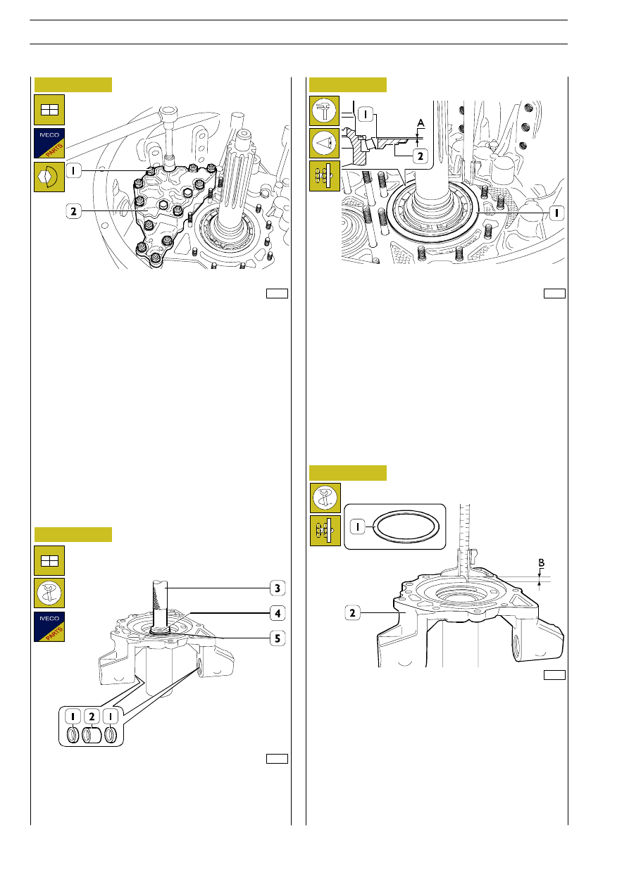
Figure 119
61211
Position a new gasket on the front cover. Mount the oil pump
(2) together with the adjustment ring (2, Figure 118).
Screw down the nuts (1) and tighten them to the required
torque.
Figure 120
61212
To replace the seals (1) and bushings (2), use general tools
to remove - fit them.
To fit the seal (5) use the keying device 99370420 (4) and
grip 99370006 (3).
530511
Drive input shaft cover
62213
Figure 121
Determine the thickness S of the drive input shaft bearing
adjustment ring as follows:
- Turn the drive input shaft and check that the outer ring
(1) rests without any clearance or pre-load on the rollers
of the internal ring of the bearing.
- Measure the protrusion of the bearing (1) from the plane
of the front cover (2), distance A.
Figure 122
61214
- Measure the depth B of the seat of the bearing (1,
Figure 121) on the cover (2).
The thickness S of the adjustment ring (1) is determined by
the following equation:
S= [ B - (A - C)] - D
Where:
-
A - B, measurements taken;
-
C, thickness of gasket;
-
D, end float of 0 - 0.1 mm.
92
GEARBOX ZF 16 S 151 D.D. - 181 D.D./O.D. - 221 D.D.
S
TRALIS
AT/AD
Base - January 2003