Iveco Stralis AT/AD. Manual - part 72


  Index      Iveco     Iveco Stralis AT/AD - service repair manual 2003 year


Search            


Content   ..  70  71  72  73   ..


Iveco Stralis AT/AD. Manual - part 72


37625

37627

37626

37628

37629

37630

Figure 43

Figure 44

Figure 45

Figure 46

Figure 47

Figure 48

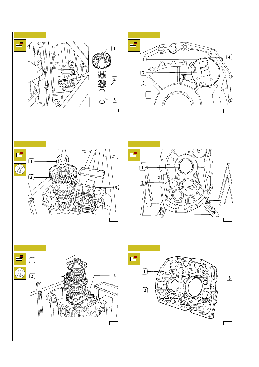
Set the gearbox vertical, with the ouput side turned down-
ward. Use a punch to remove the shaft (3) from the box, then
withdraw the Reverse speed transmission gear (1) c.w.the two
roller bearings (2).

Screw eyebolt 99360502 (1) to the transmission shaft (2), en-
gage the eyebolt to a hoister, move the main shaft (3) side-
ways, then remove the transmission shaft from the gearbox.

Engage hook 99370449 (1) to the main shaft (2), engage the
shaft to a hoister, then remove the main shaft (2) c.w.fork (3)
from the gearbox.

Remove the spring retaining ring (1), then remove the plate
(2) and the locking fork (4). Keep the spring (3).

Withdraw the outer rings of rear bearings of main (1) and
transmission (2) shafts from the gearbox.

Remove the outer rings of the front bearings of main (3) and
transmission (1) shafts from the front cover (2).

24

GEARBOX ZF 9 S 109 D.D.

S

TRALIS

AT/AD

Base - January 2003

31015

30071

Figure 49

GEARBOX COMPONENTS

Figure 50

COMPONENTS IN INNER GEAR ENGAGEMENT CONTROLS

GEARBOX ZF 9 S 109 D.D.

25

S

TRALIS

AT/AD

30475

31016

30477

30478

31017

Figure 51

Figure 52

Figure 53

Figure 54

Figure 55

Use the puller (1) shown in the figure and clamp (2) to remove
the cone (3) of the taper roller bearing from the input shaft (4).

Clamp the main shaft in a vice and remove the hook
99370449. Remove the sliding sleeve (1) that engages III and
IV speeds and check that springs (2), pawls (3) and small blocks
(4) do not come out. Keep these components.

Use the puller (1) shown in the figure, the thrust block
99345097 (2) and clamp (4) to remove the cone (3) of the
taper roller bearing from the main shaft (5).

Remove the spring retaining ring (1). Use the puller (5) with
relevant grips set under the synchronizer (3) and clamp (6) to
remove the ring and hub (2).
Remove the coupling element (4).

Remove the III speed gear (1) and relevant roller bearing (2).

!

This operation is to be carried out only where the
bearing is to replace.

531020

REMOVING THE MAIN SHAFT

26

GEARBOX ZF 9 S 109 D.D.

S

TRALIS

AT/AD

Base - January 2003

REMOVING THE INPUT SHAFT

30481

31019

31018

30483

30484

30485

Figure 56

Figure 57

Figure 58

Figure 59

Figure 60

Figure 61

Remove the spring retaining ring (1). Use puller (8), with the
handles set under the coupling element (5), the clamp (9) and
the thrust block 99345097 (7) to remove the bush (2) and the
gear (3) with the coupling element (5). Remove the roller
bearing (4) and the synchronizer ring (6).

Remove the sliding sleeve (1) that engages 2nd and 1st speed
and check that the pawls (2 and 4) and the spring (3) do not
come out. Keep such components.

Use puller 99347101 (4), grips and ring 99347148 (5) to re-
move the hub (1) of the sliding sleeve that engages 2nd and
1st speeds. Remove the synchronizer ring (2) and the coupling
element (3).

Remove the 1st speed gear (1) and relevant roller bearing (2).

Upturn the main shaft (3). Remove the spring retaining ring
(1). Use the puller (4), block 99345097 (5) and the clamp (6)
to remove the planet gears (2).

Use the puller (3), the thrust block 99345097 (4) and the
clamp (5) to remove the R speed gear (2) and the cone (1)
of the taper roller bearing.

GEARBOX ZF 9 S 109 D.D.

27

S

TRALIS

AT/AD


Content   ..  70  71  72  73   ..