Iveco Stralis AT/AD. Manual - part 48


  Index      Iveco     Iveco Stralis AT/AD - service repair manual 2003 year


Search            


Content   ..  46  47  48  49   ..


Iveco Stralis AT/AD. Manual - part 48


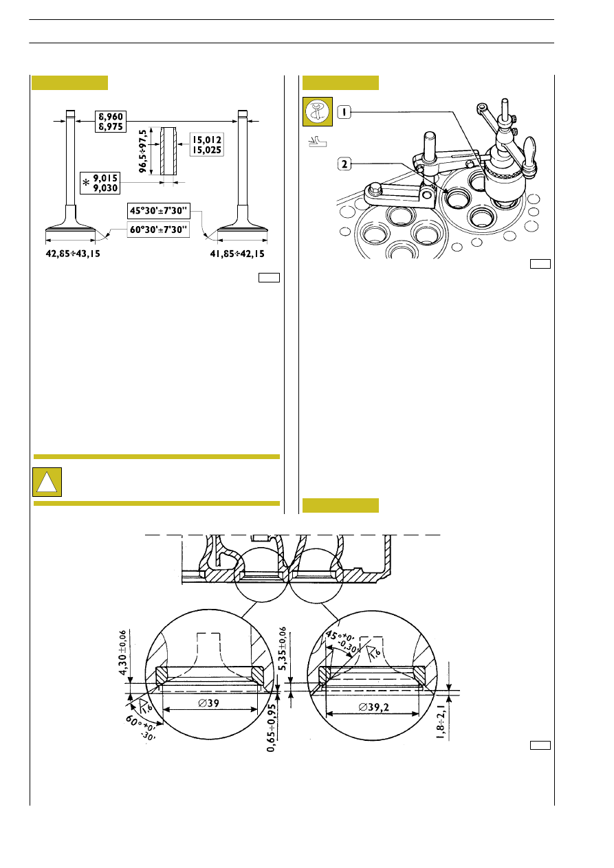
MAIN DATA OF VALVES AND VALVE GUIDES

* Measurement to be made after driving in the valve guides

Check with a micrometer that the diameter of the valve
stems is as indicated. If necessary, grind the valve seats with
a grinding machine, removing as little material as possible.

Figure 116

60617

540661

Valve seats

Regrinding — replacing valve seats

!

The valve seats are reground whenever the valves or
valve guides are ground and replaced.

41032

Check the valve seats (2). If you find any slight scoring or
burns, regrind them with tool 99305019 (1) according to the
angles shown in Figure 116 and Figure 118. If it is necessary
to replace them, using the same tool and taking care not to
affect the cylinder head, remove as much material as possible
from the valve seats so that, with a punch, it is possible to
extract them from the cylinder head.

Heat the cylinder head to 80 — 100

°C and, using a drift, fit in

the new valve seats (2), chilled beforehand in liquid nitrogen.
Using tool 99305019 (1), regrind the valve seats according
to the angles shown in Figure 118.

After regrinding the valve seats, using tool 99370415 and dial
gauge 99395603, check that the position of the valves in
relation to the plane of the cylinder head is:

-

-0.65 to -0.95 mm (recessing) intake valves;

-

-1.8 to -2.1 mm (recessing) exhaust valves.

Figure 117

73537

Figure 118

MAIN DATA OF VALVE SEATS

1. Intake valve seat — 2. Exhaust valve seat

1

2

S

TRALIS

AT/AD

178

F3A ENGINE

Base - January 2003

60619

To replace the injector case (2), proceed as follows:

- Thread the case (2) with tool 99390804 (1).

The steps described in Figs. 120 — 123 — 124 — 125 need to
be carried out by fixing the tools, with the bracket A, to the
cylinder head.

Checking clearance between valve-stem and
associated valve guide

Using a dial gauge with a magnetic base, check the clearance
between the valve stem and the associated guide. If the
clearance is too great, change the valve and, if necessary, the
valve guide.

The valve guides are removed with the drift 99360481.
They are fitted with the drift 99360481 equipped with part
99360295.
Part 99360295 determines the exact position of assembly of
the valve guides in the cylinder head. If they are not available,
you need to drive the valve guides into the cylinder head so
they protrude by 30.8-31.2 mm.
After driving in the valve guides, rebore their holes with the
smoother 99390311.

540667

Valve guides

Replacing valve guides

73538

* Measurement to be made after driving in the valve guides

Figure 119

Figure 120

540613

Replacing injector cases

Removal

179

S

TRALIS

AT/AD

F3A ENGINE

60621

- Using the tool 99390772 (2) remove any residues (1) left

in the groove of the cylinder head.

- Screw the extractor 99342149 (2) into the case (3).

Screw down the nut (1) and take the case out of the
cylinder head.

60620

60622

- Lubricate the seals (3) and fit them on the case (4). Using

tool 99365056 (2) secured to the cylinder head with
bracket A, drive in the new case, screwing down the
screw (1) upsetting the bottom portion of the case.

60623

- Using the reamer 99394041 (1-2), rebore the hole in the

case (3).

Figure 121

Figure 122

Figure 123

Figure 124

S

TRALIS

AT/AD

180

F3A ENGINE

Base - January 2003

60624

47585

Check injector protrusion (2) with the dial gauge (1).
The protrusion must be 1.14 to 1.4 mm.

Checking injector protrusion

71720

INJECTOR CASE ASSEMBLY DIAGRAM

Figure 125

- Using grinder 99394041 (1-2), ream the injector seat in

the case (3), check the injector protrusion from the
cylinder head plane which must be 1.14 to 1.4 mm.

Figure 126

Figure 127

181

S

TRALIS

AT/AD

F3A ENGINE


Content   ..  46  47  48  49   ..