Iveco Daily. Manual - part 416


  Index      Iveco     Iveco Daily - service repair manual 2004 year


Search            


Content   ..  414  415  416  417   ..


Iveco Daily. Manual - part 416


190

ELECTRIC/ELECTRONIC SYSTEM

D

AILY

Base - May 2004

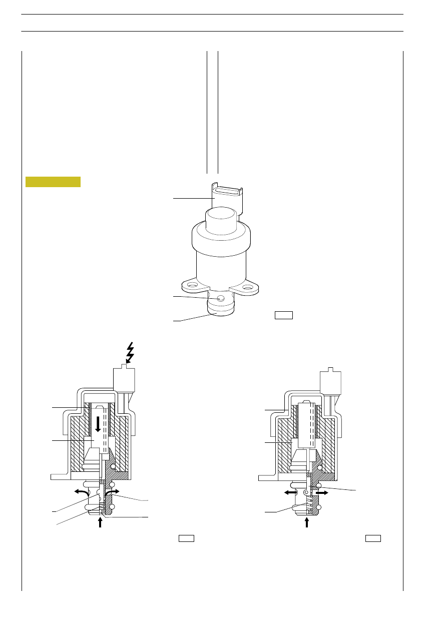
When  the  engine  control  centre  pilots  the  pressure

regulator via the PWM signal, solenoid (1) is activated, which

in its turn generates movement of magnetic core (2).
Core movement causes cylinder (3) axial displacement by

fuel delivery partialization.

When  solenoid  (1)  is  not activated, the magnetic core is

moved to its rest position by preload spring (6).
In  these  conditions,  cylinder  (3)  is  in  a  position  to  offer

maximum fuel passage cross-section.
Control  electro  valve  78013  is  connected  to  centre

connector A pins 19 and 49.

1. Solenoid - 2. Magnetic core - 3. Cylinder - 4. Fuel input - 5. Fuel output - 6. Preloiad spring - 7. Connector

7

5

4

1

2

3

4

5

1

2

6

3

6

Figure 209

003386t

75574

75575

ELECTRIC/ELECTRONIC SYSTEM

191

D

AILY

Rail (pressure accumulator) F1C

The hydraulic accumulator is mounted in the cylinder head

on the side opposite aspiration.
By its volume, it damps fuel pressure oscillations owing to:

- high-pressure pump operation
- electro injector opening.
On hydraulic accumulator there is located the fuel pressure

sensor.

Pressure sensor

Fitted to a rail end, it measures fuel pressure present to the purpose of determining existing fuel pressure. Pressure value is used

to control pressure and determine injection electric control duration (85157).

It is connected to the central unit at pins A 8/43/28. It is fed at 5 V.

1. Rail - 2. Pressure sensor

PRESSURE LIMITER OPERATING GRAPH

1500 bar

0 bar

0.2V

0.5V

4.5V

4.8V

Minimum

1500 bar

0 bar

0.2V

4.8V

VOLTAGE

PRESSURE

Figure 210

Figure 211

88418

192

ELECTRIC/ELECTRONIC SYSTEM

D

AILY

Base - May 2004

engine aspiration manifold.
The gauge is of the heated film type and is located o their

aspiration conduit between the turbine and the air filter.
The gauge contains the aspired air temperature sensor.
It is connected to the central unit on connector "A".
Pin 1 sensor - Pin A37 - temperature signal
Pin 2 sensor - Power supply (+15)
Pin 3 sensor - Pin A44 - mass
Pin 4 sensor - Pin A29 - reference voltage
Pin 5 sensor - Pin A42 - pressure signal
* If present

The  operating  principle  is  based  on  a  heated  membrane

inserted  in  a  measurement  canal  through  which  air  to  the

engine flows.
The hot film membrane is kept at  a  constant  temperature

some 120 °C above incoming air level by the heating resistor.
The  air  mass  traversing  the  measurement  canal  tends  to

subtract heat from the membrane so current must cross the

resistor to maintain constant film temperature.
Current absorbed is proportional to the air mass flowing to

the engine and is measured with a Wheatstone bridge and the

signal is forwarded to the electronic centre.

GAUGE

1. Connector - 2. Gauge body - 3. Air input grid

TECHNICAL VIEW OF GAUGE CONNECTOR

Figure 212

Figure 213

003333t

003334t

ELECTRIC/ELECTRONIC SYSTEM

193

D

AILY

Air temperature/pressure sensor 

(without EGR)

This  component  incorporates  a  temperature  sensor  and  a

pressure sensor (85156).
It is fitted on the engine intake manifold and measures the

maximum  flow  rate  of  the  intake  air  which  is  used  to

accurately calculate the amount of fuel to be injected at each

cycle.
It is connected to the central unit on connector "A".
Pin 1 sensor - Pin A23 -  earth -
Pin 2 sensor - Pin A53 -  temperature signal
Pin 3 sensor - Pin A13 -  5V  - supply -
Pin 4 sensor - Pin A40 -

0 ÷ 5V

pressure signal

Course of sensor in relation to the temperature
Temperature

Resistance

- 40 °C

48.50 kOhm

- 20 °C

15.67 kOhm

0 °C

5.86 kOhm

20 °C

2.50 kOhm

40 °C

1.17 kOhm

60 °C

0.59 kOhm

80 °C

0.32 kOhm

100 °C

0.18 kOhm

120 °C

0.11 kOhm

Course of sensor in relation to the pressure:
See graph opposite.

AIR FLOW METER

AIR FLOW METER CONNECTION

2.5 bar

0.2 bar

0.4V

4.65V

VOLTAGE

ABSOLUTE PRESSURE

AIR FLOW METER OPERATING GRAPH

Figure 214

Figure 215

Figure 216

8660


Content   ..  414  415  416  417   ..