Iveco Daily. Manual - part 417


  Index      Iveco     Iveco Daily - service repair manual 2004 year


Search            


Content   ..  415  416  417  418   ..


Iveco Daily. Manual - part 417


194

ELECTRIC/ELECTRONIC SYSTEM

D

AILY

Base - May 2004

This is integrated inside the control unit.
It measures the atmospheric pressure to correct the flow rate

in relation to the altitude.

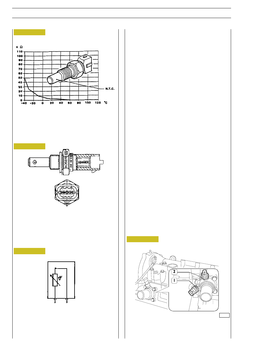
Engine coolant temperature sensor

This is an NTC sensor located on the thermostat box.
It  detects  the  temperature  of  the coolant fluid to give the

control  unit  information  about  the  engine  temperature

conditions.
It is connected to pins 58 and 41 of connector A of the control

unit.
Course of the sensor in relation to the temperature:
Temperature

Resistance

- 40°C

48.30 kOhm

- 20°C

15.46 kOhm

Ą Ą0°C

5.89 kOhm

Ą 20°C

2.50 kOhm

Ą 40°C

1.17 kOhm

Ą 60°C

0.59 kOhm

Ą 80°C

0.32 kOhm

 100°C

0.19 kOhm

 120°C

0.11 kOhm

Fuel temperature sensor

This is an NTC sensor located on the fuel filter.
It detects the temperature of the fuel to give the control unit

information about the fuel oil temperature conditions.
It is connected to pins 52 and 51 of connector A of the control

unit.
It  is  exactly  the  same  as  the  engine  coolant  temperature

sensor.

COURSE OF SENSOR RESISTANCE IN RELATION TO

TEMPERATURE

TECHNICAL VIEW OF ENGINE COOLANT

TEMPERATURE SENSOR

WIRING DIAGRAM

NTC

LOCATION OF ENGINE COOLANT TEMPERATURE

SENSOR

1. EDC signal - 2. Signal instrument panel

Figure 217

Figure 219

003324t

Figure 218

Figure 220

ELECTRIC/ELECTRONIC SYSTEM

195

D

AILY

Fuel filter

Cartridge degree of filtering: 5 micron
Differential operating pressure (obstruction indicator): 0.6 bar
The fuel temperature sent by the sensor to the electronic injection control unit allows very accurate calculation of the flow rate

of the fuel to be injected in the cylinders.
It is located in a fairly accessible position in the left front part of the engine compartment.
1. Actuated by ECU via relay with fuel temperature below 3°C.
2. Filtering element
3. Shows presence of water through a warning lamp on instrument panel.
4. Differential pressure sensor calibrated at 0,6 bar : any clogging is shown by warning lamp
5. It is a NTC sensor connected to EDC for fuel temperature reading enabling electronic control to calculate the amount of

diesel oil to be injected into the cylinders.

6. Installed on filter support for excess fuel return to tank.

1. Clogged filter sensor Ć 2. Fuel temperature sensor Ć 3. Water sensor Ć 4. Heater

1

2

3

4

3

1

2

4

Figure 221

003312t

196

ELECTRIC/ELECTRONIC SYSTEM

D

AILY

Base - May 2004

On brake pedal there are two switches; an N.C. (53565) is

directly  connected  to  the  central  unit  at  pins  K17-K80.  It

provides signals (voltages) in order to warn the central unit

about occurred braking.
Second switch 53501 N.A. provides a voltage for turning on

stop lights.

Clutch pedal switch

An  N.C.  switch  connected  to  electronic  centre  pin  K58  is

mounted on the clutch pedal (42374).
The clutch pedal actuated signal" is used by the centre to

identify gear condition selected and gear shifts.
In  absence  of  the  pedal  pressed  switch  signal,  the  centre

disenables the Cruise Control function.

1. Brake pedal switches

1. Clutch pedal switch

Figure 222

Figure 223

003327t

003326t

ELECTRIC/ELECTRONIC SYSTEM

197

D

AILY

Injectors

The solenoid valve controls the lift of the atomiser needle.
On  the  fuel  inlet  union  a  filter  protects  the  injector  for

impurities.  The  injector  is  constructively  the  same  as

conventional  ones,  except  that  there  is  no  needle  return

spring.
Access  to  the  injectors  is  gained  by  releasing  the  side

soundproof cover from the cylinder head. The fuel recovery

pipe has a quick coupling.
The injector comprises two parts:
- actuator - atomiser composed of pressure rod (1), pin

(2) and nozzle (3)

- control  solenoid  valve  comprising  a  coil  (4)  and  drive

valve (5).

1

st

 phase: rest position

The coil (4) is not activated and the shutter (6) is in the closed

position.
The same fuel pressure acts in both the control area (7) and

in the pressure chamber (8), but as the shutter (6) is closed,

the needle (2) cannot be raised.
2

nd 

phase: start of injection

The coil (4) is energised and causes the shutter (6) to move

upwards.
The fuel of the control volume (9) flows towards the backflow

duct (10) causing a drop in the pressure in the control area

(7).
At the same time, the pressure of the fuel in the pressure

chamber (8) causes the needle (2) to rise, resulting in fuel

injection to the cylinder.
3

rd

 phase: end of injection

The coil (4) is not activated and makes the shutter (6) return

to the closed position, which re-creates a balance of forces

that makes the needle (2) return to the closed position and

consequently end injection.
Injectors (78247)
The solenoid valve is of the N.C. type.
The injectors are connected individually to the control unit at

the following pins:
- A16 / A47 cylinder 1 injector
- A2 / A31 cylinder 2 injector
- A1 / A46 cylinder 3 injector
- A17 / A33 cylinder 4 injector

INJECTOR WIRING DIAGRAM AND CROSS SECTION

1. Pressure rod - 2. Needle - 3. Nozzle - 4. Coil - 5. Pilot

valve - 6. ball shutter - 7. control area - 8. pressure

chamber - 9. Control volume - 10. Backflow duct -

11. Control duct - 12. Supply duct - 13. Electrical

connection - 14. High pressure fuel inlet - 15. Spring

10

4

5
6

7

12

13

9

11

14

12

1

15

2

8

3

Figure 224


Content   ..  415  416  417  418   ..