Iveco Daily. Manual - part 406


  Index      Iveco     Iveco Daily - service repair manual 2004 year


Search            


Content   ..  404  405  406  407   ..


Iveco Daily. Manual - part 406


152

ELECTRIC/ELECTRONIC SYSTEM

D

AILY

Base - May 2004

engine aspiration manifold.
The gauge is of the heated film type and is located o their

aspiration conduit between the turbine and the air filter.
The gauge contains the aspired air temperature sensor.
It is connected to the centre on pins A5 / A17 / A18 / A26

/ A28.

Pin 1 sensor - Pin A5 ECU - temperature signal
Pin 2 sensor - Pin A17 ECU - 5V power supply
Pin 3 sensor - Pin A18 ECU - mass
Pin 4 sensor - Pin A26 ECU - reference voltage
Pin 5 sensor - Pin A28 ECU - pressure signal

The  operating  principle  is  based  on  a  heated  membrane

inserted  in  a  measurement  canal  through  which  air  to  the

engine flows.
The hot film membrane is kept at  a  constant  temperature

some 120 °C above incoming air level by the heating resistor.
The  air  mass  traversing  the  measurement  canal  tends  to

subtract heat from the membrane so current must cross the

resistor to maintain constant film temperature.
Current absorbed is proportional to the air mass flowing to

the engine and is measured with a Wheatstone bridge and the

signal is forwarded to the electronic centre.

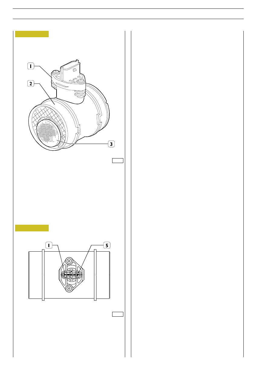
1. Connector - 2. Gauge body - 3. Air input grid

TECHNICAL VIEW OF GAUGE CONNECTOR

Figure 164

Figure 165

003333t

003334t

ELECTRIC/ELECTRONIC SYSTEM

153

D

AILY

Atmospheric pressure sensor

This is integrated inside the control unit.
It measures the atmospheric pressure to correct the flow rate

in relation to the altitude.

Engine coolant temperature sensor

This is an NTC sensor located on the thermostat box.
It  detects  the  temperature  of  the coolant fluid to give the

control  unit  information  about  the  engine  temperature

conditions.
It is connected to pins 1 and 30 of connector A of the control

unit.
Course of the sensor in relation to the temperature:

Temperature

Resistance

- 40°C

48.30 kOhm

- 20°C

15.46 kOhm

Ą Ą0°C

5.89 kOhm

Ą 20°C

2.50 kOhm

Ą 40°C

1.17 kOhm

Ą 60°C

0.59 kOhm

Ą 80°C

0.32 kOhm

 100°C

0.19 kOhm

 120°C

0.11 kOhm

Fuel temperature sensor

This is an NTC sensor located on the fuel filter.
It detects the temperature of the fuel to give the control unit

information about the fuel oil temperature conditions.
It is connected to pins 15 and 30 of connector A of the control

unit.
It  is  exactly  the  same  as  the  engine  coolant  temperature

sensor.

COURSE OF SENSOR RESISTANCE IN RELATION TO

TEMPERATURE

TECHNICAL VIEW OF ENGINE COOLANT

TEMPERATURE SENSOR

WIRING DIAGRAM

NTC

LOCATION OF F1A ENGINE COOLANT

TEMPERATURE SENSOR

1. EDC - 2. Signal instrument panel signal

003324t

Figure 166

Figure 167

Figure 168

Figure 169

154

ELECTRIC/ELECTRONIC SYSTEM

D

AILY

Base - May 2004

type with incorporated N.O. minimum switch.
It gives the electronic control unit a value proportionate with

the  operating  angle  of  the  pedal  itself  determining  fuel

delivery.
It is supplied at 5 Volt.
The potentiometer resistance is approx. ~ 1 kOhm.
It is connected at pins 2, 13, 27, 29 and 35 of connector B of

the control unit.

LOCATION OF SENSOR ON ACCELERATOR PEDAL

SENSOR WIRING DIAGRAM

Figure 170

Figure 171

ELECTRIC/ELECTRONIC SYSTEM

155

D

AILY

Brake pedal switches

Two switches are located on the brake pedal; N.C. 53565 si

connected directly to electronic centre pin B31 and 53501 is

connected to the centre via remote switch 25006 for stop

light  actuation  and  to  generate  a  redundant  signal  on  the

centre increasing system reliability degree.

Clutch pedal switch

An  N.C.  switch  connected  to  electronic  centre  pin  B38  is

mounted on the clutch pedal.
The clutch pedal actuated signal" is used by the centre to

identify gear condition selected and gear shifts.
In  absence  of  the  pedal  pressed  switch  signal,  the  centre

disenables the Cruise Control function.

1. Brake pedal switches

1. Clutch pedal switch

Figure 172

Figure 173

003326t

003327t


Content   ..  404  405  406  407   ..