Iveco Daily. Manual - part 404


  Index      Iveco     Iveco Daily - service repair manual 2004 year


Search            


Content   ..  402  403  404  405   ..


Iveco Daily. Manual - part 404


144

ELECTRIC/ELECTRONIC SYSTEM

D

AILY

Base - May 2004

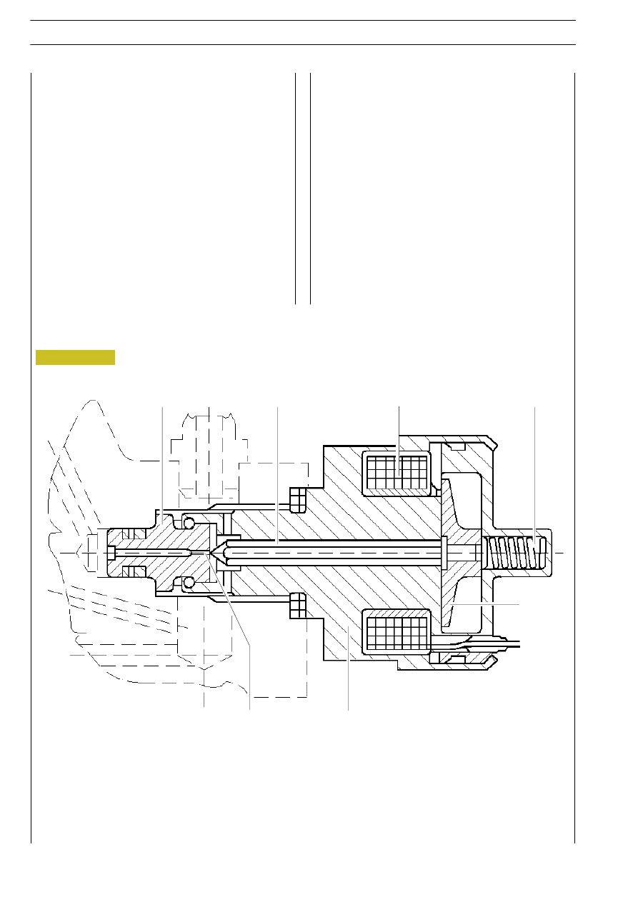
This is located on the high pressure pump and modulates the

fuel pressure to the rail (and thus to the injectors) on the

basis of the commands received from the electronic control

unit.
It mainly comprises:
- a ball shutter (1)
- a valve (3) control pin (2)
- a preloading spring (4)
- a coil (5)
When the solenoid is not energised, the delivery pressure

depends only on the spring preload.

When,  after  processing  the  various  engine  operating

parameters, the electronic control unit determines the need

for a different injection pressure, it modulates a command

signal  in  PWM  to  the  regulator  solenoid  valve  which

discharges the excess pressure in the pump backflow duct.
The modulated pressure is checked through the pressure

sensor  on the rail by the control unit, which, if necessary,

suitably  modifies  the  intensity  of  the  command  signal  to

reach the required result.
The control solenoid valve (78013) is connected to pins 9

and 20 of connector A of the control unit.

PRESSURE REGULATOR CROSS SECTION

1. Ball shutter - 2. Ppin - 3. Valve - 4. Preloading spring - 5. Coil - 6. Body - 7. Anchor

3

2

5

4

7

6

1

Figure 150

ELECTRIC/ELECTRONIC SYSTEM

145

D

AILY

Pressure regulator (F1A)

Similar to the one installed on the 8140 engine and mounted

on the CP3 pump low-pressure circuit.
When  the  engine  control  centre  pilots  the  pressure

regulator via the PWM signal, solenoid (1) is activated, which

in its turn generates movement of magnetic core (2).
Core movement causes cylinder (3) axial displacement by

fuel delivery partialization.

When  solenoid  (1)  is  not activated, the magnetic core is

moved to its rest position by preload spring (6).
In  these  conditions,  cylinder  (3)  is  in  a  position  to  offer

maximum fuel passage cross-section.
Control  electro  valve  78013  is  connected  to  centre

connector A pins 9 and 20.

1. Solenoid Ć 2. Magnetic core Ć 3. Cylinder Ć 4. Fuel input Ć 5. Fuel output Ć 6. Preloiad spring Ć 7. Connector

7

5

4

1

2

3

4

5

1

2

6

3

6

Figure 151

003386t

75574

75575

146

ELECTRIC/ELECTRONIC SYSTEM

D

AILY

Base - May 2004

The volume of the rail is small in size (29 cc) to allow quick

pressurising when starting, at idle speed and in the event of

high loads.
It  has  however  sufficient  volume  to minimise the plenum

effect caused by opening and closing of the injectors and

operation of the high pressure pump.

Screwed onto the rail there is a fuel pressure sensor. The

signal sent by this sensor to the electronic control unit is

feedback information on the basis of which correct actuation

of the rail pressure is checked.

Common Rail for engines with serial numbers over 3089322
Temporary solution with simulated flow limiters and over pressure valve connected to the fuel discharge unit.

1

2

5

4

3

Common Rail for engines produced since end-October 2000
Final Common Rail solution without flow limiters and over pressure valve. The new Common Rail features different pressure

sensor layout and discharge unit connection predisposition.

1

2

3

4

5

1. Common Rail - 2. Simulated flow limiter - 3. Simulated over pressure valve seat - 4. Pressure sensor - 

5. Fuel input from high-pressure pump

1. Common Rail - 2. To electrical injectors - 3. Pressure sensor - 4. Fuel discharge unit attachment - 

5. Fuel input from high-pressure pump

Figure 152

Figure 153

ELECTRIC/ELECTRONIC SYSTEM

147

D

AILY

Rail (pressure accumulator - F1A)

The hydraulic accumulator is mounted in the cylinder head

on the side opposite aspiration.
Its some 22-cm

3

 volume dampens fuel pressure oscillations

due to:

- high-pressure pump operation
- electro injector opening.
The fuel sensor and overpressure valve are positioned on

the hydraulic accumulator.

Over pressure valve
The over pressure valve protects system components in

the event that fuel pressure exceeds rated 1750 bars.
A The piston's conical end normally keeps discharge to

tank open.

B In the event of fuel pressure being over 1750 bars in

the rail, the piston is relocated and excess pressure is

discharged into the tank.

2

1

3

4

5

1. Common rail - 2. To electro injectors - 3. Fuel pressure sensor - 4. Overpressure valve - 

5. Fuel input from high pressure pump

IVER PRESSURE VALVE

1. Body - 2. Piston - 3. Stop - 4. Spring - 5. Direct

discharge to tank - 6. Seat on the rail

Figure 154

Figure 155

75576

70500

70502


Content   ..  402  403  404  405   ..