Iveco Daily. Manual - part 385


  Index      Iveco     Iveco Daily - service repair manual 2004 year


Search            


Content   ..  383  384  385  386   ..


Iveco Daily. Manual - part 385


104

ELECTRIC/ELECTRONIC SYSTEM

D

AILY

Base - May 2004

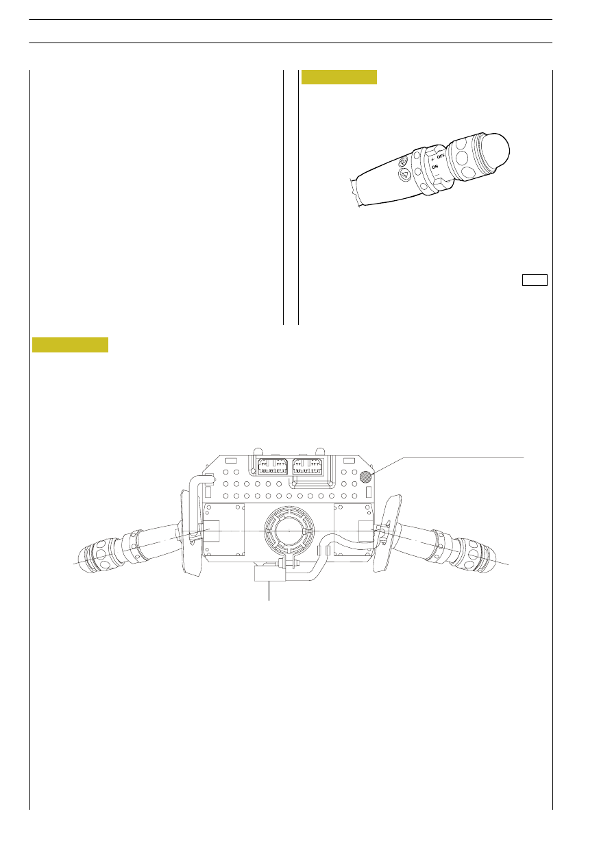
The cruise control is operated by push-buttons (Figure 102)

installed on the windscreen wiper control lever with following

functions:
- adjust engine idle speed;
- read and adjust drive rpm;
- set and store travel speed.
Cruise control is deactivated by pressing the clutch pedal, the

brake pedal and keeping the accelerator pedal pressed for

over 10 seconds or by turning the switch to OFF".
Cf. the Use and Maintenance Handbook on board the vehicle

for further information on use.

CRUISE CONTROL

TECHNICAL VIEW OF THE COMPONENT

A. Connector  (Cruise control)

EEC HOMOLOGATION STAMP AREA

A

Figure 102

Figure 103

000245t

ELECTRIC/ELECTRONIC SYSTEM

105

D

AILY

ELECTRONIC SYSTEMS
Immobilizer

In order to increase protection against attempted theft, the vehicles have been fitted with an electronic engine block system called

"Immobilizer"  which  is  activated  automatically  removing  the  ignition  key.  In  fact,  the  keys  are  fitted  with  an  electronic

Transponder" that sends a code signal to a special electronic control unit which, only allows the engine to be started if it

recognises the code sent. del motore.

WARNING LIGHT MAIN SYSTEM COMPONENTS

1. Immobilizer electronic control unit - 2. Electronic key containing the transponder - 3. Aerial used for sending/reading

the key code - 4. Code card containing the code for emergency starting

4

2

3

1

EDC

Figure 104

000245t

106

ELECTRIC/ELECTRONIC SYSTEM

D

AILY

Base - May 2004

Electronic control unit
This is located behind the steering wheel column.
It is able to communicate with "EDC" central unit by a "CAN line".
The main functions of the control unit are:
- recognising insertion and rotation of the key in the ignition switch,
- activating and reading the secret code emitted by the Transponder,
- managing control and processing the codes,
- communicating with the "EDC" control unit,
- memorising any faults,
- system diagnostics.

Pin

Function

A1

Aerial

A2

Aerial

A3

Ċ

B1

CAN line L for EDC control unit pin 39 (EDC 16 - pin 61)

B2

Line K for 38-pin diagnostic connector pin 12

B3

Negative for Immobilizer failure warning lamp

B4

CAN H line for EDC control unit pin 8 (EDC 16 - pin 62)

B5

Ċ

B6

Earth

B7

Key-operated positive supply

B8

Ċ

B

A

1

3

8

4

1 3

Figure 105

00290t

ELECTRIC/ELECTRONIC SYSTEM

107

D

AILY

Electronic keys
An electronic device called Transponder" is fitted in the key

grip which is not supplied by any battery, it is not removable

and contains and transmits the secret code.
Inserting the key, the Transponder" is activated, then, when

it receives the radio waves emitted by the aerial (fitted on the

ignition  switch  block),  it  automatically  answers  transmitting

the secret code.
If the two codes correspond, the control unit enables starting,

otherwise it shuts off the flow of fuel thereby preventing the

engine from starting.

Aerial
This is fitted coaxially with the ignition switch and it has the

task of:
- supplying the energy to the Transponder" for sending

the secret code

- receiving the signal from the Transponder and sending it

to the control unit.

It is connected to the control unit on pins A1/A2.

ELECTRONIC KEYS

AERIAL

!

The  keys  provided  are  two.  Each  key  contains  a

Transponder" with the corresponding secret code.

It  is  highly  to  carry  out  the  correct  key  teaching

procedure.

Figure 106

Figure 107

000291t

8659

000292t


Content   ..  383  384  385  386   ..