Iveco Daily. Manual - part 341


  Index      Iveco     Iveco Daily - service repair manual 2004 year


Search            


Content   ..  339  340  341  342   ..


Iveco Daily. Manual - part 341


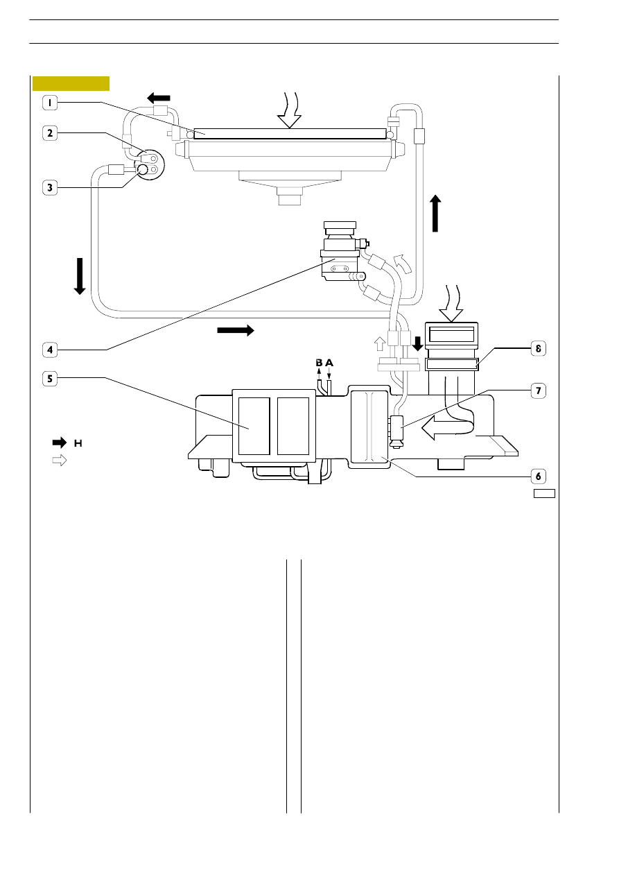
A. Refrigerant liquid inlet - B. Refrigerant liquid outlet - H. High-pressure circuit - L. Low-pressure circuit.

1. Condenser - 2. Three-level pressure switch - 3. Drier filter - 4. Compressors - 5. Heater/fan unit - 6. Evaporator -

7. Expansion valve - 8. Pollen filter.

AIR-CONDITIONING AND HEATING
Description

This is accomplished by integrating an air-conditioning and a
heating system.

This integration makes it possible to change the temperature
and humidity in the cab.

Air-conditioning

Air-conditioning is accomplished by taking advantage of the
high capacity of some gases to lower temperature
considerably in their phase of expansion, thereby making it
possible to absorb heat from the cab.

This condition is obtained by two different levels of pressure
(high, when the refrigerant fluid is in its liquid state, and low,
when the fluid is in its gaseous state) that are established and
maintained during operation of the system.

52279

Figure 2

Heating

Heating is accomplished by a radiator, in the heater unit, in
which the engine coolant circulates.

Special doors allow air to pass through the radiator only
when the heating function is activated.

The main components of the air-conditioning and heating
system comprise:
- compressor (4);
- condenser (1);
- drier filter (2);
- three-level pressure switch (3);
- expansion valve (7);
- evaporator (6);
- heater/fan unit (5);
- pollen filter (8).

L

6

CAB AIR-CONDITIONING

D

AILY

AIR-CONDITIONING SYSTEM MAIN COMPONENTS AND FUNCTIONAL DIAGRAM

52280

Figure 3

The automatic air-conditioning/heating system is controlled
by

an

electronic

control

unit

that

governs

the

air-conditioning and heating functions so as to obtain and
maintain the required conditions in as stable a manner as
possible.

1. Air-conditioning system filler coupling (high pressure) - 2. Pollen filter - 3. Air-conditioning system drainage

coupling (low pressure) - 4. Low-pressure pipe - 5. High-pressure pipe - 6. High-pressure pipe - 7. Condenser -

8. High-pressure pipe - 9. Drier filter - 10. Three-level pressure switch - 11. Compressor - 12. 5A fuse

(air-conditioner/heater) - 13. 5A fuse (engine electronic control unit) - 14. 5A fuse (miscellaneous lighting) -

15. 30A fuse (cab heater) - 16. 10A fuse (engine electronic control unit) - 17. 3A fuse (air-conditioner) -

18. 3A fuse (panel) - 19. Contactor turning off air-conditioner compressor - 20. Contactor turning on air-conditioner

compressor - 21. Contactor controlling electromagnetic coupling - 22. 25A fuse (engine electronic control unit) -

23. Fuse/contactor-holder unit - 24. Heater/air-conditioner unit.

The following figure illustrates the vehicle layout of the main
components of the automatic air-conditioning/heating
system and the layout of the contactors and fuses on the
fuse/contactor-holder unit.

Description

CAB AIR-CONDITIONING

7

D

AILY

AUTOMATIC AIR-CONDITIONING/HEATING

The condenser is a heat exchanger located between the
compressor and the drier filter. Its function is to transform the
refrigerant fluid from its gaseous to its liquid state.

This transformation is made by the refrigerant fluid releasing
heat to the outside air. This is why the condenser is installed
on the vehicle so as, in the best conditions, to take advantage
of the air stream produced by the forward motion of the
vehicle.

When the vehicle is stationary or in a traffic jam, the flow of
air needed to transform the refrigerant fluid is produced,
under the control of the three-level pressure switch, by the
fan for cooling the engine coolant.

52281

52282

52283

52284

Figure 4

Figure 5

The compressor is located between the evaporator and the
condenser. Its function is to:
- draw refrigerant fluid in the form of vapour at low

pressure and low temperature from the evaporator
through the inlet (2);

- compress the refrigerant fluid drawn up and introduce

it at high temperature and high pressure into the
condenser through the outlet (1).

The compressor is driven by the electromagnetic friction
device mounted on the compressor shaft.

The electromagnetic friction device is composed of an
electromagnetic coil (2), a pulley (1) and a front disc (3).

When the system is not running, the pulley (1) turns idle on
the bearing (4) since it is driven by the engine via the V-belt.

On

switching

on

the

air-conditioning

system,

the

electromagnetic coil (2) attracts the front disc (3) on the
pulley (1) that comes to be virtually keyed onto the
compressor shaft and makes it rotate.

The drier filter is located between the condenser and the
expansion valve. It has the following functions:
- reserve tank for excess refrigerant fluid during variable

filling phases;

- filtering element for the solid particles generated by

compressor wear;

- eliminating the moisture formed in the system.

553234

Drier filter

553239

Compressor

553232

Condenser

Figure 6

Figure 7

8

CAB AIR-CONDITIONING

D

AILY

MAIN COMPONENTS

52285

52286

Figure 8

Figure 9

The expansion (block) valve is located between the drier
filter and the evaporator.

Its function is to control and proportion the flow of
refrigerant fluid to get the highest refrigerating capacity out
of the system and to lower the pressure of the refrigerant (at
the filter outlet) to a pre-set value so that the fluid, circulating
in the evaporator, can be drawn up by the compressor in a
completely gaseous form.
This valve has two passages for the refrigerating fluid:

- the bottom one enabling the refrigerant to pass (5) from

the drier filter to the evaporator (2). Along this route
there is a spring (4) that, appropriately set, makes it
possible to obtain such a leap in temperature
(overheating) as to make sure that the refrigerant, at the
evaporator inlet, is entirely in its gaseous state. In
addition, there is also a modulating element, in this case
a ball (3) housed in the gauged pipe that controls the
flow rate of refrigerant to the evaporator;

- the top one enabling the refrigerant to pass (1) from the

evaporator to the compressor (6). Along this route
there is a temperature sensor (7) that, depending on the
temperature at the evaporator outlet, makes it possible
to control the flow rate of refrigerant, by means of the
modulating element (3), and control the overheating, by
means of the spring (4).

The evaporator is a heat exchanger located between the
expansion valve and the compressor.

Its function is to:
- change the state of the refrigerant from a liquid, at the

inlet, to a gas, at the outlet;

- absorb the heat in the cab and thereby produce the

required refrigerating effect.

To be able to perform these functions, an electric fan draws
warm, moist air from the cab and conveys it onto the
evaporator.

Since this air is at a higher temperature than the refrigerant,
it gives some of its heat to the refrigerant and cools down,
while the moisture it contains condenses on the evaporator
fins in the form of droplets.

This produces cold, dehumidified air.

This change takes place with considerable heat absorption.
A special channel collects the condensation formed and
discharges it outside.

The considerable cooling of the radiating pack is due to the
change in state, from liquid to gas, of the refrigerant.

553233

Expansion valve

553231

Evaporator

CAB AIR-CONDITIONING

9

D

AILY


Content   ..  339  340  341  342   ..