Iveco Daily. Manual - part 327


  Index      Iveco     Iveco Daily - service repair manual 2004 year


Search            


Content   ..  325  326  327  328   ..


Iveco Daily. Manual - part 327


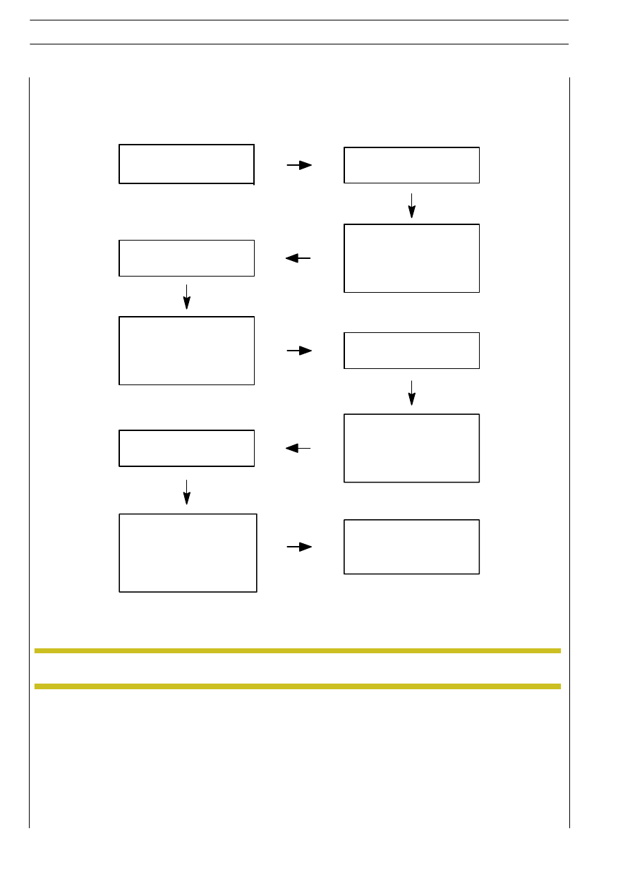
After rear right wheel bleeding

has been completed (as

signalled by the diagnosis

instrument), close the drain

screw. The procedure will

now be completed.

ABS 8/ESP 8 system bleeding procedure sequence

Call the “BLEEDING”

routine.

Open the rear right wheel

drain screw.

In case of failure of one single

step or the entire bleeding

process, the whole procedure

will have to be repeated.

After front right wheel

bleeding has been completed

(as signalled by the diagnosis

instrument), close the drain

screw and proceed with the

rear right wheel

After front left wheel bleeding

has been completed (as

signalled by the diagnosis

instrument), close the drain

screw and proceed with the

front right wheel.

Open the front right wheel

drain screw.

After rear left wheel bleeding

has been completed (as

indicated by the diagnosis

instrument), tighten the drain

screw and then proceed with

the front left wheel.

Open the front left wheel

drain screw.

Open the drain screw of the

corresponding wheel.

After air bleeding from the braking circuit has been completed, fill with brake fluid up to the top level (do not fill with
oil that has already been used).

NOTE

48/2

HYDRO-PNEUMATIC SYSTEM - BRAKES

D

AILY

Revi - February 2005

Regulation of load proportioning valve on
vehicle

To stop the vehicle from skidding or the wheels from being
locked when braking, you must check the device at regular
intervals and eventually adjust if necessary. This consists in
verifying the values indicated on the plate (Figure 37) applied
on the inside of the bonnet.

PERFORMANCE CURVE

A. Inlet pressure (Bar) - B. Outlet pressure (bar)
Ratio = 0.25

!

If there is no plate or if the data is missing, ask the
manufacturer for a duplicate by indicating:

- Vehicle type
- Number of leaf springs
- Vehicle pitch
- Weight of rear axle
- Number of load proportioning valve

- loosen the nut (1);
- connect a weight (A, page 50) to the plate (5) at point

(2);

- tighten the nut (1) at the specified torque and remove

the loads (A and B).

- start up the engine;

784310

Mechanically controlled load sensing
valve (vehicles 35C - 40C - 45C - 50C

- 60C - 65C)

The load proportioning valve automatically adjusts, as a function
of the load acting on the rear axle, the braking torque produced
by the brakes of the axle itself. This valve has the important job,
especially when the vehicle is light without any load, to limit the
braking torque that would otherwise block the rear wheels with
a consequent skidding and jerking of the vehicle.

52386

52385

52387

52388

Figure 35

Figure 36

Figure 37

Figure 38

LOAD PROPORTIONING VALVE PLATE

The operations are to be carried out in the following order:
- set the vehicle with its rear wheel on a weighing machine

99336914 or on the brake test bench;

- connect the pressure gauges 99372269 or Modus to the

pressure

test

points

upstream

from

the

load

proportioning valve;

- if the pressure gauges are not equipped with a valve for

automatic bleeding, bleed off the air through the
pressure gauges by unscrewing the appropriate ring nuts;

- load the vehicle so as to have a load (B) on the rear axle

divided equally between the right- and left-hand sides of
the vehicle with a tolerance of

±5 kg;

HYDRO-PNEUMATIC SYSTEM - BRAKES

49

D

AILY

Base - May 2004

To check the load sensing valve, all the components of the
braking system must be in full working order. In addition, in the
case of replacing the leaf springs for special versions it is
necessary to install a new rating plate whose values are correct.

- with the engine idling and a pressure of 100 bar, shown

on the pressure gauge (3) upstream from the sensing
valve, check that the outlet pressure shown on the
pressure gauge (2) downstream from the sensing valve
corresponds to the values given on the rating plate,
otherwise replace the sensing valve;

- Proceed as follows if the pressure read downstream of

the corrector do not correspond to the values shown in
Figure 37.

- Disconnect the bar (4, Figure 38) from the axle.

- in addition, use the transmission lever (3, Figure 38) to

check that the load sensing valve stem runs smoothly in
its seat, otherwise replace the sensing valve;

- reconnect the adjustment rod (4, Figure 38) to the rear

axle;

784310

Dual mechanically controlled load
sensing valve (vehicles 29L - 35S)

!

Perform the check by gradually increasing the
pressure.

- Once the checks have been completed, verify the

operation of the brakes by testing them.

TABLE OF LOADS FOR ADJUSTING THE LOAD
SENSING VALVE

52389

52390

Figure 39

Figure 40

Figure 41

The load sensing valve automatically regulates the braking
torque generated by the brakes of the rear axle according to
the load weighing on the rear axle.
It has the important function, especially when the vehicle has no
load, of limiting the braking torque that would lock the rear
wheels causing the vehicle to skid.

A. Inlet pressure (in bar) - B. Outlet pressure (in bar)
Ratio = 0.15

Adjusting the load sensing valve

52391

This adjustment is similar to that described above,
using the following loads.

TABLE OF LOADS FOR ADJUSTING THE LOAD
SENSING VALVE

3

Model

Load (A)

Load (B)

kg

kg

35C

3.5

1500

40C

3

1500

45C

4

1800

50C semi-elliptic and
double flex. parabolic leaf springs 9

1800

50C single flex. parabolic
leaf springs.

4.5

1800

Model

Load (A)

Load (B)

kg

kg

29L

9

1500

35S

6,5

1500

- Load the vehicle to obtain the loading sequence shown

in the table in fig. 37, equally shared on the rear axle on
the left and right sides of the vehicle with a tolerance of
± 5 kg.

50

HYDRO-PNEUMATIC SYSTEM - BRAKES

D

AILY

Base - May 2004

The devices described below are integrated into three
different types of systems:
- ABS 5.3 system, which integrates the ABS/ABD and EBD

functions on vehicles equipped with F1A (no automatic
transmission), F1C and 8140 engines.

- ABS 8 system, which integrates the ABS and EBD

functions on vehicles equipped with F1A engine and
6 AS 300 VD automatic transmission.

- ESP8

system

(OPTION),

which

includes

the

ESP/ABS/EBD/ASR/MSR/HBA/HCC functions on vans up
to 3.5 t. with F1A/F1C engines.

ABS SYSTEM FUNCTIONS

Antilock braking system (ABS)

This system comprises an electro-hydraulic modulator and
an electronic control unit mounted on the modulator,
located in the engine bay, four sensors and four phonic
wheels that measure the number of turns of the wheels.
The tendency for one or more wheels, whether front or rear,
to lock, which is detected by the sensors through the pulses
of the phonic wheels, is communicated to the electronic
control unit that, by means of the electro-hydraulic
modulator, independently or simultaneously regulates the
pressure in the hydraulic circuit of the front and rear axles.

Electronic braking distribution device (EBD)

This system acts at a level prior to ABS operation. It ensures
a sensitive control over the tendency of the rear wheels to
lock with respect to the front ones, when braking, by
optimizing the braking force in the different conditions of
load, travel and state of use of the vehicle.
This device substitutes the function of the mechanically
operated load sensing valve. If this device fails, braking takes
place with the same pressure on front and rear brakes.

Anti-skid braking device (ABD)

This system acts by automatically braking the wheels that on
starting tend to skid.
It operates with speeds up to 40 km/h.

Electronic Stability Program (ESP) - Option

It monitors the vehicle’s behaviour steadily (both on straight
stretches and bends, when braking or accelerating).
It also monitors the driver’s actions: steering the wheel,
pressing the brake pedal, accelerator position, speed.
It is always active in the background, i.e. the ESP system
compares the actual vehicle ride with the driver’s desired ride
50 times a second. It recognizes dangerous situations before
the driver does.
The system considers the different possibilities of coming into
operation. It brakes on every single wheel separately.
It operates on the engine control system.

This function is available in ABS 5.3 systems only.

NOTE

FUNCTIONS

INCLUDED

IN

THE

ESP

SYSTEM ONLY

Acceleration drive control device (ASR)

This system prevents driving wheel skid through quick action
on the engine and brakes. It allows the vehicle to set off safely
and fast even on slippery roads or when one driving wheel
is skidding. It also reduces the risk of understeering when you
accelerate too much when cornering.

Engine braking torque control (MSR)

This system avoids driving wheel drag due to the exhaust
brake. It ensures vehicle stability when releasing on slippery
roads (e.g. snow, ice), and assists in keeping the path when
cornering and shifting down, especially on slippery roads. It
requires a slight increase of revs number, through the CAN
line.

Hill holder control (HHC)

This function allows the vehicle to be kept automatically
locked (braked) until the clutch is closet and the driver
subsequently presses the accelerator pedal, thus preventing
undesired vehicle motion.
The function is actuated automatically: the braking situation
is detected by the sensor inside the modulator. When the
brake pedal is released, the vehicle will be kept braked for 2.5
seconds, thus allowing the driver/system to put the gear (and
the vehicle to be started). This ensures safe, easy start with
any incline, regardless of the weight carried.

Hydraulic Brake Assistant (HBA)

The main feature of the HBA function is to recognize an
emergency braking situation followed by “automatic”
increase of vehicle deceleration.
Vehicle deceleration is only restricted to actuation of ABS
control, thus taking the greatest advantage of the grip
between the tyre and the roadbed currently available.
Therefore, ordinary drivers can now achieve braking
distances which only experienced drivers could achieve in
the past.
If the driver reduces the braking intensity, vehicle
deceleration is reduced depending on the reduction of the
force applied onto the pedal.
Therefore, the driver can control deceleration accurately
after overcoming the emergency situation.
The extent of the braking request from the driver
corresponds to the force applied onto the pedal. The force
applied onto the pedal is derived from

measuring the

pressure in the brake pump.

Revi - February 2005

HYDRO-PNEUMATIC SYSTEM - BRAKES

51

D

AILY


Content   ..  325  326  327  328   ..