Iveco Daily. Manual - part 328
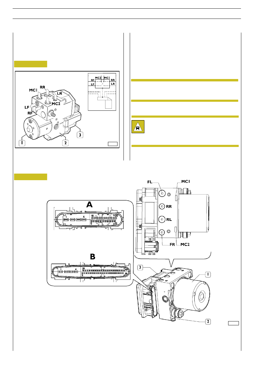
Figure 42
526716
Electro-hydraulic
modulator/control unit for 29L - 35S
vehicles
52392
ABS8/ESP8 systems
Figure 43
ABS 5.3 systems
The electronic control unit has the task of controlling the
electro-hydraulic modulator solenoid valves according to the
signals from the wheel speed sensors.
The electro-hydraulic modulator modulates the pressure of
the brake fluid in both front and rear circuits according to the
control signals from the control unit.
The devices comprising the control unit and
electro-hydraulic modulator of the various models
are not interchangeable.
NOTE
The parts inside the hydraulic unit are not
compatible with mineral oil and unsuitable fluids.
In case of contamination by such fluids, the unit
shall be replaced and properly disposed of.
1. Hydraulic accumulator - 2. Electro-hydraulic modulator - 3. Electronic control unit - A. ABS8 connector -
B. ESP8 connector - F/MC1. Front axle power supply - R/MC2. Rear axle power supply - LF (or FL for ABS8/ESP8 systems).
Left front axle output - RR. Right rear axle output - RF (or FR for ABS8/ESP8 systems). Right front axle output - LR (or RL
for ABS8/ESP8 systems) . Left rear axle output
102113
51/1
HYDRO-PNEUMATIC SYSTEM - BRAKES
D
AILY
Revi - February 2005