Iveco Daily. Manual - part 308


  Index      Iveco     Iveco Daily - service repair manual 2004 year


Search            


Content   ..  306  307  308  309   ..


Iveco Daily. Manual - part 308


YES

NO

YES

NO

YES

YES

NO

YES

NO

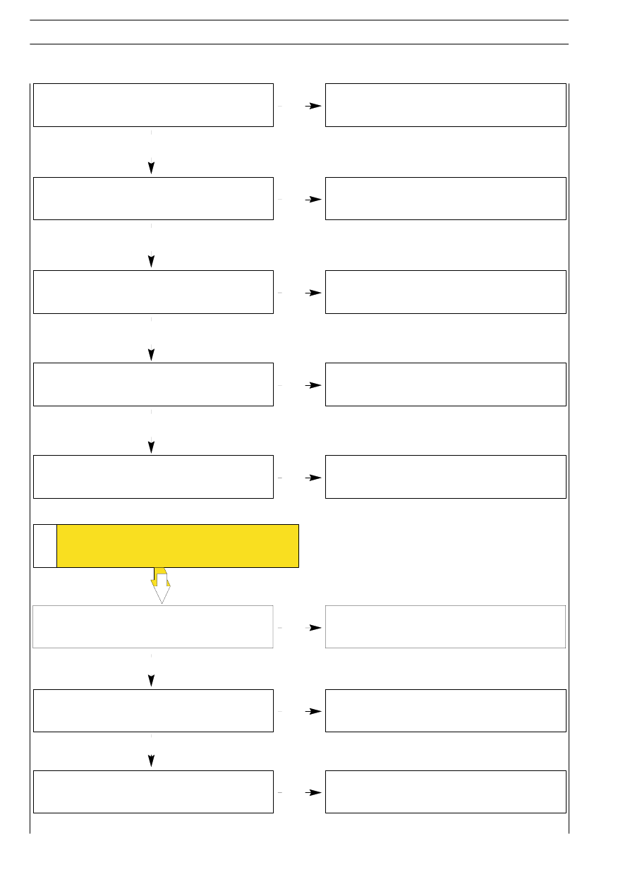
Front wheel geometry incorrect.

Check and adjust according to specifications in the section
”Axles”.

Wheels out of balance.

Balance in accordance with instructions given in the
section ”Wheels and tyres”.

Steering rod joints loose on the levers.

Replace any worn parts.

Irregular pump operation.

Replace pump.

Leakage of oil from hydraulic power steering circuit
couplings.

Check coupling seals for serviceability, replacing any
which are worn.

Adjust in accordance with characteristic data for
described in the section ”Axles”.”

Wrong wheel toe-in.

5

YES

NO

YES

TORSIONAL VIBRATION OF THE

STEERING WHEEL

YES

Wheels out of balance.

Balance in accordance with instructions given in the
section ”Wheels and tyres”.

Air in hydraulic system.

Check suction tube and pump shaft seal for leaks. Bleed
system and top up the fluid.

NO

8

STEERING GEAR

D

AILY

Base - May 2004

Play in ball joints and/or elastic supports loosen.

Play in universal joint.

NO

YES

NO

YES

6

EXCESSIVE PLAY AT THE

STEERING WHEEL

Secure the supports
Replace the ball joints.

Replace universal joint.

Replace the power steering unit

Internal failure of hydraulic power steering.

In any case it is necessary to determine the place and the reason why there is oil leakage, eliminate the cause, top up oil in
the tank with the engine started up to the upper mark of the dipstick.

7

YES

NO

YES

LOSS OF OIL

Tank cover not secured.

Secure cover.

Seal gaskets worn.

Replace the power steering unit

YES

8

INSUFFICIENT PRESSURE

IN THE CIRCUIT

Hydraulic pump not operating correctly.

Replace the power steering pump

YES

(Continue)

STEERING GEAR

9

D

AILY

Base - May 2004

Oil leaking from couplings in power steering
circuit.

YES

NO

YES

Check coupling seals for serviceability, replacing any
which are worn.

Insufficient oil level in the tank.

Top up level and bleed circuit.

9

THE VEHICLE TENDS TO

MOVE SIDEWARDS

Replace the power steering unit

Check the windings and in case replace oil pressure
sender.

Oil pressure sender malfunction.

10

YES

NO

HYDRAULIC POWER STEERING PILOT

LIGHT ALWAYS LIGHTED

YES

Hydraulic power steering oil level low.

Top up oil.

10

STEERING GEAR

D

AILY

Base - May 2004

The power steering system consists of:
- a tank (A);

- a blade pump (B) with delivery regulating valves (C);

- a series of connecting pipings (D);

- an hydraulic power steering (E).
The oil tank, in the engine compartment, feeds the blade pump.
This pump is able to provide a feeding pressure ranging from
a minimum of approx. 4 bar to a maximum of approx. 80 + 10.
The oil come to the steering box, which is similar to a
mechanical steering as for general building features, from the
pump.
In fact, its operation is mechanical for pinion to rack coupling,
The rack rod is joined to the wheels with two side tie rods.
The system is self-bleeding; bleeding is performed by
completely steering to the right or to the left with the engine
started and the vehicle stopped.
The oil level check must be performed with the engine started.

The description below concerns the TRW hydraulic
power steering and due to their similarity, it also
applies to the ZF hydraulic power steering.

The distributor consists of:
- a drive shaft (1) (joined to the steering column);

- a distributing valve (4);

- a wrench bar (3);

- a pinion (6).
The drive shaft is elastically joined by the wrench bar to the
pinion by means of the pin (2). The distributing valve, trigged
on the drive shaft is integral with the pinion by means of a pin
(5); it has holes and splines in order to receive and distribute
the oil flow to the hydraulic cylinder. Besides, a stiff joint (A)
ensures the mechanical working of the hydraulic power
steering in case of failure of the hydraulic system, through a
bayonet joint.

24103

Figure 2

24104

Figure 3

The hydraulic part of the steering box consist of:

- a distributor (3);

- an hydraulic cylinder (1);

- a double-acting piston (4) integral with the rack rod.

The hydraulic connection between distributor and hydraulic
cylinder is achieved using two stiff pipes (2). The distributor (3)
is integral with the hydraulic power steering pinion.

HYDRAULIC POWER STEERING SYSTEM DIAGRAM

HIGH PRESSURE

LOW PRESSURE

A

6

1

3

2

4

5

1

2

3

4

E

NOTE

STEERING GEAR

11

D

AILY

Base - May 2004

POWER STEERING
Description


Content   ..  306  307  308  309   ..