Iveco Daily. Manual - part 294


  Index      Iveco     Iveco Daily - service repair manual 2004 year


Search            


Content   ..  292  293  294  295   ..


Iveco Daily. Manual - part 294


Refitting

Removal

Set the vehicle on level ground. Lock the front wheels with
chocks. Loosen the screws securing the rear wheels.

Put the bracket 99370617 on a hydraulic lift, position it under
the rear axle and lift the vehicle.
Rest the chassis frame on stands, keeping the bracket in
contact with the rear axle.

Take out the nuts securing the wheels with tool 99321024.

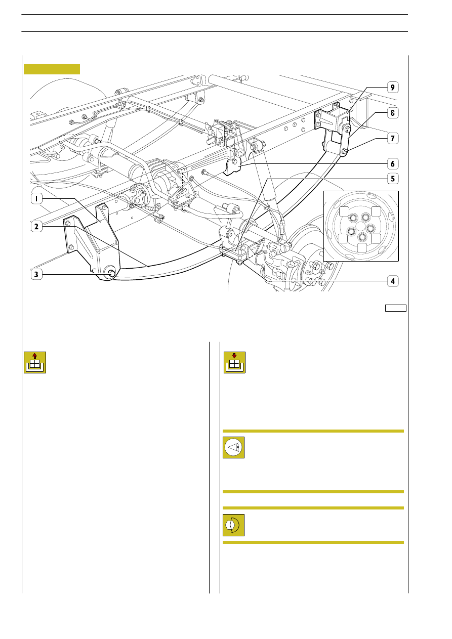
Take out the nuts (4) and remove the brackets (5) joining the
leaf springs (2) to the rear axle.

Position the trolley 99306064 under the leaf spring (2) and
fasten this to the trolley support with the brackets.

Take out the nuts and remove the screw (3) securing the leaf
spring (2) to the front mounting (1).

Take out the nut and remove the screw (7) securing the leaf
spring (2) to the shackle (8) of the rear mounting (9).

Lower the trolley 99306064 and extract the leaf spring.

Figure 91

REAR SUSPENSION WITH SINGLE-BLADE PARABOLIC LEAF SPRING

Check the threads of brackets which fasten the leaf
springs to the axle; if they are damaged, re-machine
the threads (operation 500412) or replace the
brackets.

Tighten the nuts to the prescribed driving torque.
Following the order shown in the figure.

After replacing the leaf springs and the hydraulic shock
absorbers, it is necessary to check the efficiency of the braking
control and, if necessary, carry out its adjustment (operation
796910. See Braking System Section).

To re-fit, carry out the removal operations in reverse, taking
the following precautions.

50972A

Check the conditions of bumpers (6), if they are damaged,
replace them (operation 500417).

1

4

2

5

3

A

78

REAR MECHANICAL SUSPENSIONS

D

AILY

REAR LEAF SPRING
Vehicles: 29 L - 35 S

Removal

Set the vehicle on level ground. Lock the front wheels with
chocks. Loosen the screws securing the rear wheels.
Put the bracket 99370617 on a hydraulic lift, position it under
the rear axle and lift the vehicle rest the chassis frame on
stands, keeping the bracket in contact with the rear axle.
Take out the nuts securing the wheels with tool 99321024.
Take out the nuts (5) and remove the brackets (4) joining the
leaf springs (3) to the rear axle.
Position the trolley 99306064 under the leaf spring and fasten
this to the trolley support with the brackets.
Take out the nut and remove the screw (2) securing the leaf
spring (3) to the front mounting (1).
Take out the nut and remove the screw (8) securing the leaf
spring (3) to the shackle (7) of the rear mounting (6).
Operating the hydraulic lift, lower the rear axle to be able to
remove the centring setscrew of the leaf spring from it and
extract the leaf spring.

!

When lowering the rear axle, make sure the brake
system pipes are not put under strain.

Figure 92

REAR SUSPENSION WITH SEMI-ELLIPTICAL LEAF SPRING

Check the threads of brackets which fasten the leaf
springs to the axle; if they are damaged, re-machine
the threads (operation 500412) or replace the
brackets.

Check the conditions of bumpers (9), if they are
damaged, replace them.

Tighten the nuts to the prescribed driving torque.
Following the order shown in the figure.

After replacing the leaf springs and the hydraulic shock
absorbers, it is necessary to check the efficiency of the braking
control and, if necessary, carry out its adjustment (operation
796910. See Braking System Section).

Refitting

To re-fit, carry out the removal operations in reverse, taking
the following precautions.

50973

REAR MECHANICAL SUSPENSIONS

79

D

AILY

Vehicles: 35 C - 40 C - 45 C - 50 C - 60 C - 65 C

Assembling the leaf spring

Ensure that the leaf contact surfaces are perfectly smooth and
clean.
Before re-assembling the leaves, grease contact surfaces with
a little of CA IG Grease.
Re-assemble the pack as follows (see Figure 93):

- place the main leaf (1) with the end eyes in the end pin

of the 1st leaf (4);

- place the other leaves, included the one with the clip (5),

near the former ones, rest them on one side and align
them in the bench vice;

- insert through the central hole of the leaves, the central

pin (7), then lock the pack in the vice;

- insert the nut (2) on the central pin (7) and lock;

- close the two side retaining clamps (5) by folding the ends

back as shown in the figure.

Side clips (5) fastened with a rivet (6) to the leaf, can
be re-used, provided that they do not show signs of
breakage when they are re-bent to hold the pack. In
this case, it is necessary to replace them with new
ones to be fixed to the leaf with new rivets.

Place the leaf spring in the vice of the suitable bench, clamping
it near the central pin; remove the relevant nut and extract the
central coupling pin.

Unscrew the fastening nut (2) of the central pin (7) and
extract the pin. Open the pack side clips (5), lifting the two
ends that are bent on the main leaf. Open the vice and
disassemble the leaf spring.

Disassembling the leaf spring

19075

Figure 93

!

Leaf springs must be disassembled only Figure 93 if it
is necessary to replace the main leaf (1) or the first leaf
(4), in this case go on as follows.

In case other leaves are broken or yielded, replace the
whole leaf spring.

19074

!

Checks

Carefully clean, with diesel oil or solvent, all
components; ensure that the bushes are firmly driven
in the spring eyes and shackles.
Check that the internal surface is not ovalized and that
the pins are not worn or strained, in case they are,
replace them.

Figure 94

500454

Replacing the bushings

1

2

3

4

5

6

7

The leaf spring bushings (3) are replaced with the hydraulic
press and a suitable punch.

80

REAR MECHANICAL SUSPENSIONS

D

AILY

REPAIRS

Refitting

To re-fit shock absorbers carry out the removal
operations in reverse and comply with the prescribed
torques.

Removal

REAR AXLE SHOCK ABSORBERS VEHICLES 29 L - 35 S

Figure 95

REAR AXLE SHOCK ABSORBERS VEHICLES 35 C - 65 C

Figure 96

50975

50977

Remove the shock absorber (1) extracting the upper
and lower fastening nuts or bolts (

⇐) of the shock

absorber.

REAR MECHANICAL SUSPENSIONS

81

D

AILY

500940

REAR SHOCK ABSORBERS


Content   ..  292  293  294  295   ..