Iveco Daily. Manual - part 280
Refitting
52327
52328
74994
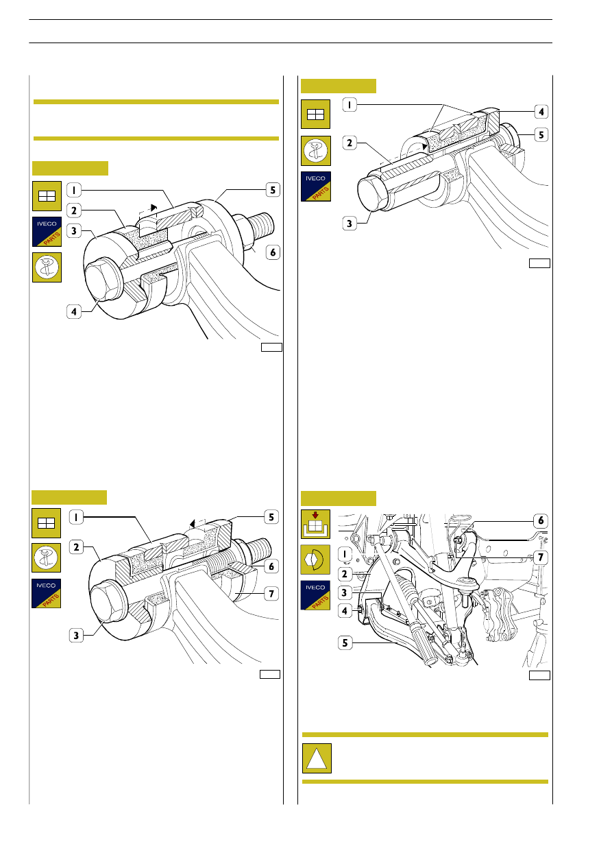
Figure 17
Figure 18
Figure 19
Insert the bushing (7) into the suspension arm (1).
Apply the parts (2 - 3 - 5 - 6) of the tool 99374179, as shown
in the figure.
Screw on the nut (6) to make the bushing (7) flush with the
suspension arm (1).
Remove the parts of tool 99374179.
Insert the spacer (2) into the bushing (1).
Apply the parts (3 - 4 - 5) of the tool 99374179, as shown
in the figure.
Screw on the nut (5) to fully insert the spacer (2) into the
flexible bushings (1).
To refit the bottom (5) and top (1) suspension arms to the
crosspiece (2), reverse the steps described for removal
tightening the nuts (6 - 3) for the fixing screws (4 - 7) to the
prescribed torque.
!
Self-locking nuts, once removed, must be replaced
with new ones.
52326
Figure 20
Insert the bushing (2) into the suspension arm (1).
Apply the parts (3 - 4 - 5 - 6) of the tool 99374179, as shown
in the figure.
Screw on the nut (6) to make the bushing (2) flush with the
suspension arm (1).
Remove the parts of tool 99374179.
Assembly
The flexible bushings of the bottom suspension arms
are equipped with metal reinforcement.
NOTE
22
FRONT MECHANICAL SUSPENSIONS
D
AILY
Base - May 2004