Iveco Daily. Manual - part 278
14
FRONT MECHANICAL SUSPENSIONS
D
AILY
Base - May 2004
Models:
29 L - 35 S - 35 C
Mannesmann - Sachs
Arvin Meritor
Distance between centre of eyes:
Open
(mm)
405
3
Closed
(mm)
320
3
Stroke
(mm)
85
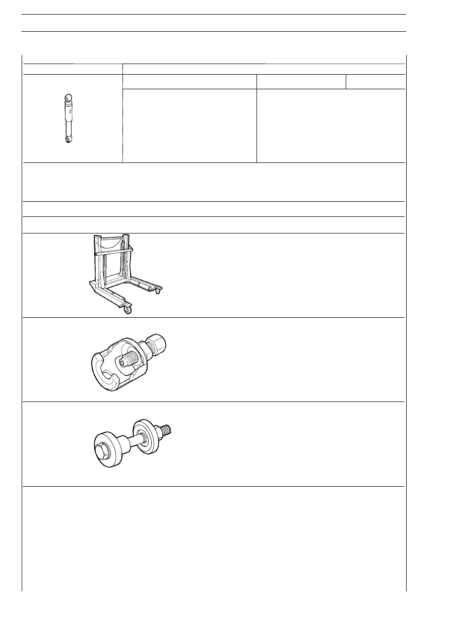
TOOLS
TOOL NO.
DESCRIPTION
Hydraulic trolley for wheel removal and refitting
99321024
99347074
Extractor to take out link pins
99374179
Tool for disassembling and reassembling suspension arm flexible bushings