Iveco Daily. Manual - part 194
51431
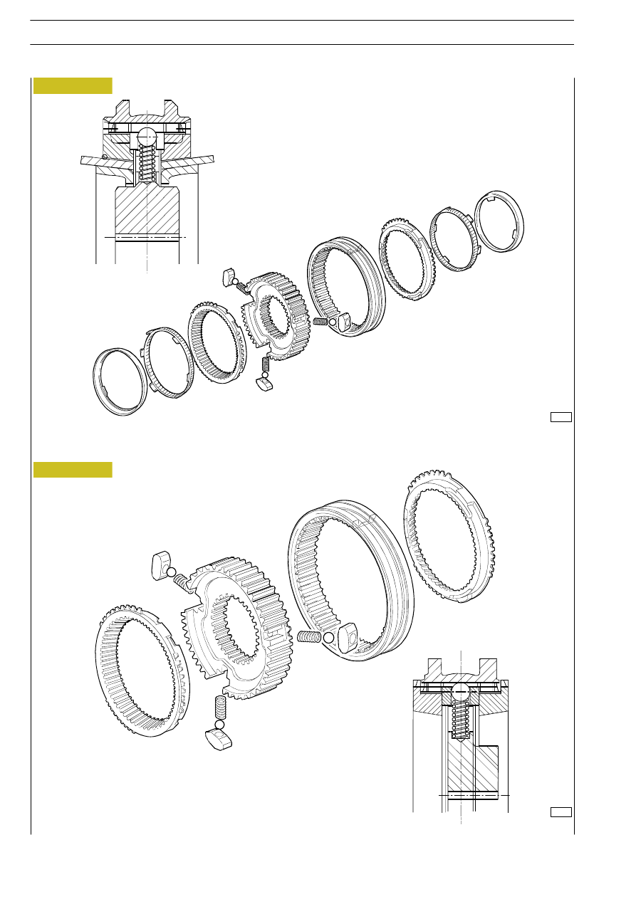
Figure 62
Figure 63
1
st
-2
nd
GEAR DUAL CONE SYNCHRONIZER ASSEMBLY
3
rd
- 4
th
- 5
th
GEAR SINGLE CONE SYNCHRONIZER ASSEMBLY
75414
Revi - February 2005
32
5 S 200 - 5 S 270 - 5 S 300 - TRANSMISSIONS
D
AILY
Base - May 2004