Iveco Daily. Manual - part 193
51410
51412
51411
51413
51414
51415
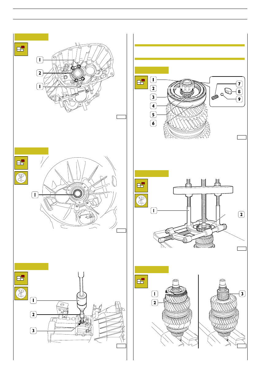
Figure 41
Figure 42
Figure 43
Figure 44
Figure 45
Figure 46
Remove the screws (1) securing the plates (2).
Take out the plates (2).
Turn over the transmission.
Using a suitable punch, remove the ball bearing (1).
Using the percussion extractor 99340205 (1) and part
99348004 (2), extract the roller bearing (3).
Clamp the main shaft (1) in a vice. Remove the roller bearing
(2) and the synchronizer ring (3). Remove the sliding sleeve
(6) for engaging 3
rd
-4
th
gear from the hub (5) and, taking care
as the plugs (8) come out with their relative balls (9) and
springs (7), recover them.
Remove the retaining ring (4, Figure 44). Extract the hub (2)
with the extractor 99348001 (1).
Remove the synchronizer ring (1), 3
rd
gear (2) and roller
bearing (3).
Disassembling the main shaft
Mark the assembly position of each synchronizing
device on the respective gears.
NOTE
Revi - February 2005
28
5 S 200 - 5 S 270 - 5 S 300 - TRANSMISSIONS
D
AILY
Base - May 2004