Iveco Daily. Manual - part 91


  Index      Iveco     Iveco Daily - service repair manual 2004 year


Search            


Content   ..  89  90  91  92   ..


Iveco Daily. Manual - part 91


75261

75263

75262

75264

75265

Figure 42

Figure 43

Figure 44

Figure 45

Figure 46

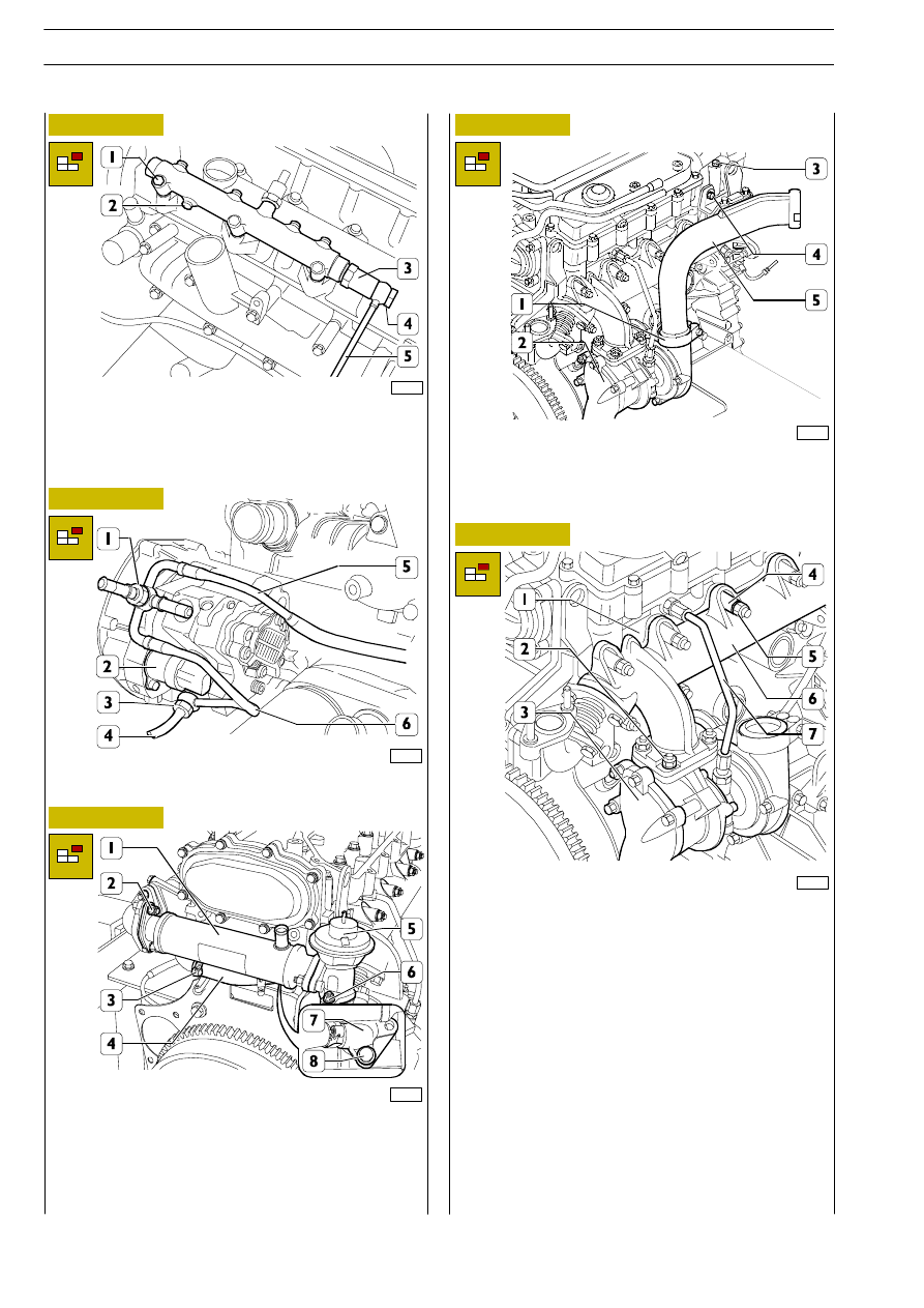
Only for forged version hydraulic accumulator, take off pipe
fitting (4) and disconnect piping (5) for fuel recovery from
overpressure valve (3).
Take out the screws (1) and remove the hydraulic
accumulator (2).

Disconnect the fuel recovery pipes (4), (5) and (6) from the
high-pressure pump (2), removing the couplings (1) and (3).

For engines with E.G.R. only
Loosen the clamp (3) and disconnect the pipe (4) from the
heat exchanger (1).
Take off the nuts (2) and (6) and remove the heat exchanger
(1) together with the E.G.R. valve (5).
Take out the screws (8) and remove the flange (7).

Take out the screw (4), loosen the clamp (1) and disconnect
the air duct (5) from the turbocharger (2) and from the
overhead (3).

Disconnect the oil pipe (7) from the coupling of the cylinder
head (1) and from the coupling of the turbocharger (3).
Take off the nuts (2) and remove the turbocharger (3) with
the associated gasket from the exhaust manifold (6).
Take off the nuts (5) and the spacers (4), remove the exhaust
manifold (6) with the associated gasket from the cylinder
head (1).

F1A ENGINE

D

AILY

342

Base - May 2004

75266

75268

75267

75269

75270

75271

Figure 47

Figure 48

Figure 49

Figure 50

Figure 51

Figure 52

Take off screws (1) and disconnect inlet manifold (2) with its
gasket.
Using wrench SP.2275 (3), remove the glow plugs (4).

Dismount sensor (3).
Take off the nut (1) and remove the timing sensor (2). Using
wrench SP.2262 (7), remove the temperature sensors (4).
Take out the screws (5) and remove the thermostat box (6).

Take out the screws (1) and remove the overhead (2).

Take off the gasket (1) and remove the hydraulic tappets
together with the rocker arms (2).

Take out the screws (1) and remove the cylinder head (2).

Block rotation of the high-pressure pump gear (1) by applying
tool SP 2263 (2) as shown in the figure. Take off the nut (3)
and remove the tool (2).

Check the protrusion of the pistons as described
under the relevant heading to check the possibility
of facing the crankcase if it has deformed.

NOTE

F1A ENGINE

343

D

AILY

Base - May 2004

75272

75274

75273

75275

75276

Figure 53

Figure 54

Figure 55

Figure 56

Figure 57

Using tool 99340035 (2), applied as in the figure, extract the
gear (1) from the shaft of the high-pressure pump (3).

Take out the screws (1) and remove the high-pressure pump
(2) from the water pump mounting (3).

Take out the screws (2) and remove the water pump
assembly (2).

Remove the plug (6) from the oil pump — vacuum pump
assembly (1).
Position the crankshaft so as to be able to insert tool
99360615 (5) into its hole through the hole in the plug (6)
and block rotation of the crankshaft.
Take out the screw (3) with the spacer (4) beneath and
remove the gear (2).

Apply tool 99340057 (4) to the front O-ring (3) of the
crankshaft and remove it from the oil pump — vacuum pump
assembly (2).
Take out the screws (1) and remove the oil pump — vacuum
pump assembly (2).

F1A ENGINE

D

AILY

344

Base - May 2004

75277

75279

75278

75280

75281

75282

Figure 58

Figure 59

Figure 60

Figure 61

Figure 62

Figure 63

Using tool 99360076 (1), remove the oil filter (2).

Take out the coupling (2) and remove the heat exchanger
(1).

Take out the screws (2) and remove the air-conditioner
compressor (1) (if applicable).

Take out the screw (2) and remove the speed sensor (1).
Take out the screws (4) and remove the compressor
mounting (3).

Take out the plug (2) with the seal (3) and extract the oil
pressure control valve (1).

Undo the screws (2) and remove the oil sump (1) with the
associated gasket and frame (3).

F1A ENGINE

345

D

AILY

Base - May 2004


Content   ..  89  90  91  92   ..