Iveco Daily. Manual - part 92
75283
75284
75285
75286
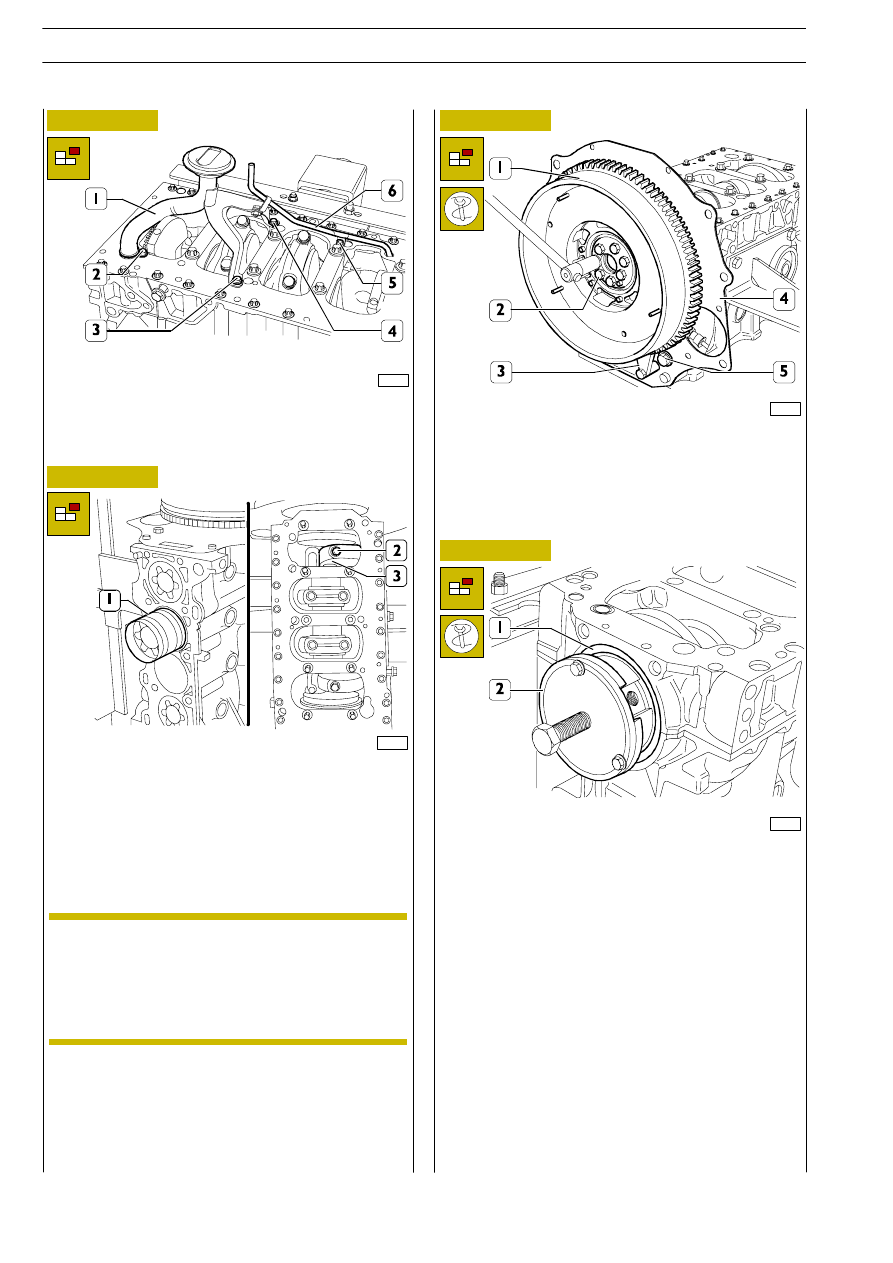
Figure 64
Figure 65
Figure 66
Figure 67
Take out the screws (2), (3), (4) and (5) and remove the
suction strainer (1) together with the pipe (6).
Take out the screws (2) and remove the connecting rod caps
(3).
Extract the pistons (1) from the top of the crankcase.
Block rotation of the flywheel (1) with tool 99360306 (3).
Take out the screws (2) and remove the engine flywheel (1).
Take out the screw (5) and remove the guard (4).
Apply tool 99340058 (2) to the rear O-ring (1) and extract
it from the crankcase.
On the same side of the connecting rod and its
associated cap, indicate the number of the cylinder
from which the connecting rod has been removed.
Keep the bearing shells in their respective housings
since, if they are used, they will need to be fitted in
the position found during removal.
NOTE
F1A ENGINE
D
AILY
346
Base - May 2004