Iveco Daily. Manual - part 32
62873
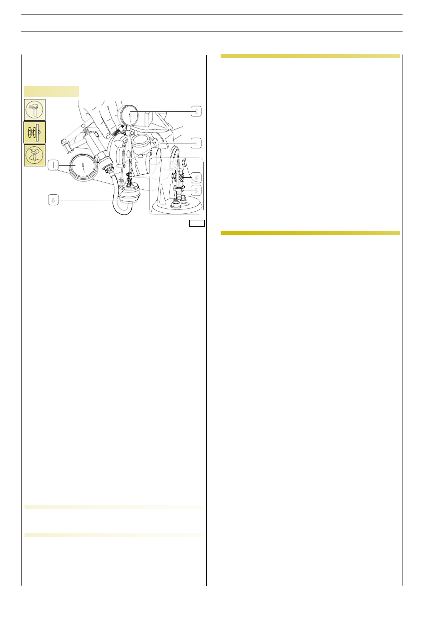
Figure 238
REPAIRS
Checking the actuator
Cover air, exhaust gas and lubricant inlets and outlets.
Clean the turbosupercharger outside accurately using
anticorrosive and antioxidant fluid and check the actuator (6).
Clamp the turbosupercharger in a vice.
Apply vacuometer 99367121 (1) pipe to actuator (6) hose.
Apply the magnetic base gauge (2) to exhaust gas inlet flange
in the turbine.
Set gauge (2) feeler pin on tie rod (3) end and set gauge (2)
to zero.
Operate the vacuum pump and check whether the tie rod (3)
stroke values correspond to the vacuum values shown in the
following table:
If a different value is found, replace the turbocharger.
During the check the vacuum value shall not fall,
otherwise the actuator shall be replaced.
NOTE
NOT ALLOWED ARE:
- any replacement or regulation of the
actuator, since the calibration of such
component is made in an optimal way
for
each
turbocharger
and
is
guaranteed for the turbocharger;
- any operation on nut (5) and ring nut
(4), since such operation does not
change engine supply characteristics
but may impair engine reliability and
duration.
Ring nut (4) is sealed with antitempering
yellow paint.
In case of engines under guarantee, each
above
specified
intervention
and/or
alteration to paint applied on ring nut (4)
causes the lapse of the guarantee.
NOTE
ENGINES 8140.43R/B/S/N
110
D
AILY
Base - May 2004
vacuum 0 mm Hg
Fully open valve
-
vacuum 150 mm Hg
Valve stroke
2.3
÷ 2.7 mm
-
vacuum 400 mm Hg
Valve stroke
9.7
÷ 10.7 mm
-
fully closed valve
Valve stroke
11
÷ 12.4 mm