Iveco Daily. Manual - part 24
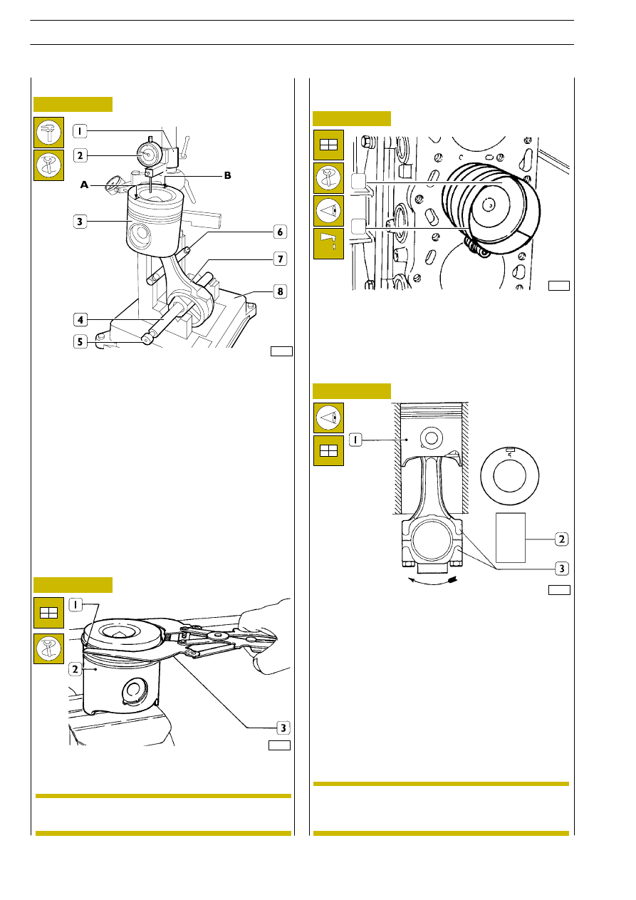
Figure 112
Figure 113
Figure 114
Figure 115
Checking for connecting rod - piston distortion
Assembling piston rings
41097
Fit piston rings (1) on piston (2), using pliers 99360183 (3).
Assembling connecting rod - piston assemblies
in cylinder barrels
18863
Lubricated pistons correctly, including piston rings and
cylinder liner interiors.
By means of ring clamp 99360605 (2) fit connecting
rod-piston assemblies (1) into cylinder liners, checking that:
- the number of each connecting rod corresponds to cap
fitting number.
1
2
45071
DIAGRAM FOR CONNECTING ROD-PISTON
ASSEMBLY FITTING INTO CYLINDER
1. Piston - 2. Accessory components group - 3. Number
printing area - A. Indirect injection engine piston
(prechamber) - *Piston crown cavity - B. Direct injection
engine piston
- piston ring openings are 120
° offset one another;
- all pistons are of same weight;
- the symbol printed on the piston crown is directed
towards flywheel, or the recess on the piston skirt
corresponds to the position of oil spray nozzles.
After assembling connecting rod-piston assembly, use tool
99395363 (8) to check squaring as follows:
- fit connecting rod (7) and piston (3) on tool 99395363
(8) chuck (4) and lock it by screw (5);
- set connecting rod (7) on bar (6);
- position dial gauge (2) support (1) so that dial gauge is
set on piston point A, with 0.5 mm preload and set dial
gauge (2) to zero;
- move chuck (4) so that dial gauge (2) is set on piston (3)
point B and check for any deviation.
61697
The piston rings for the 1
st
and 2
nd
slot must be
fitted with the word “TOP” facing upwards.
NOTE
Having not found any need to replace main
bearings, it is required to refit them in the same
order and position they were when dismantled.
NOTE
ENGINES 8140.43R/B/S/N
78
D
AILY
Base - May 2004