Iveco Daily. Manual - part 22


  Index      Iveco     Iveco Daily - service repair manual 2004 year


Search            


Content   ..  20  21  22  23   ..


Iveco Daily. Manual - part 22


23023

18923

18922

23034

6447

18518

Figure 77

Figure 78

Figure 79

Figure 80

Figure 81

Figure 82

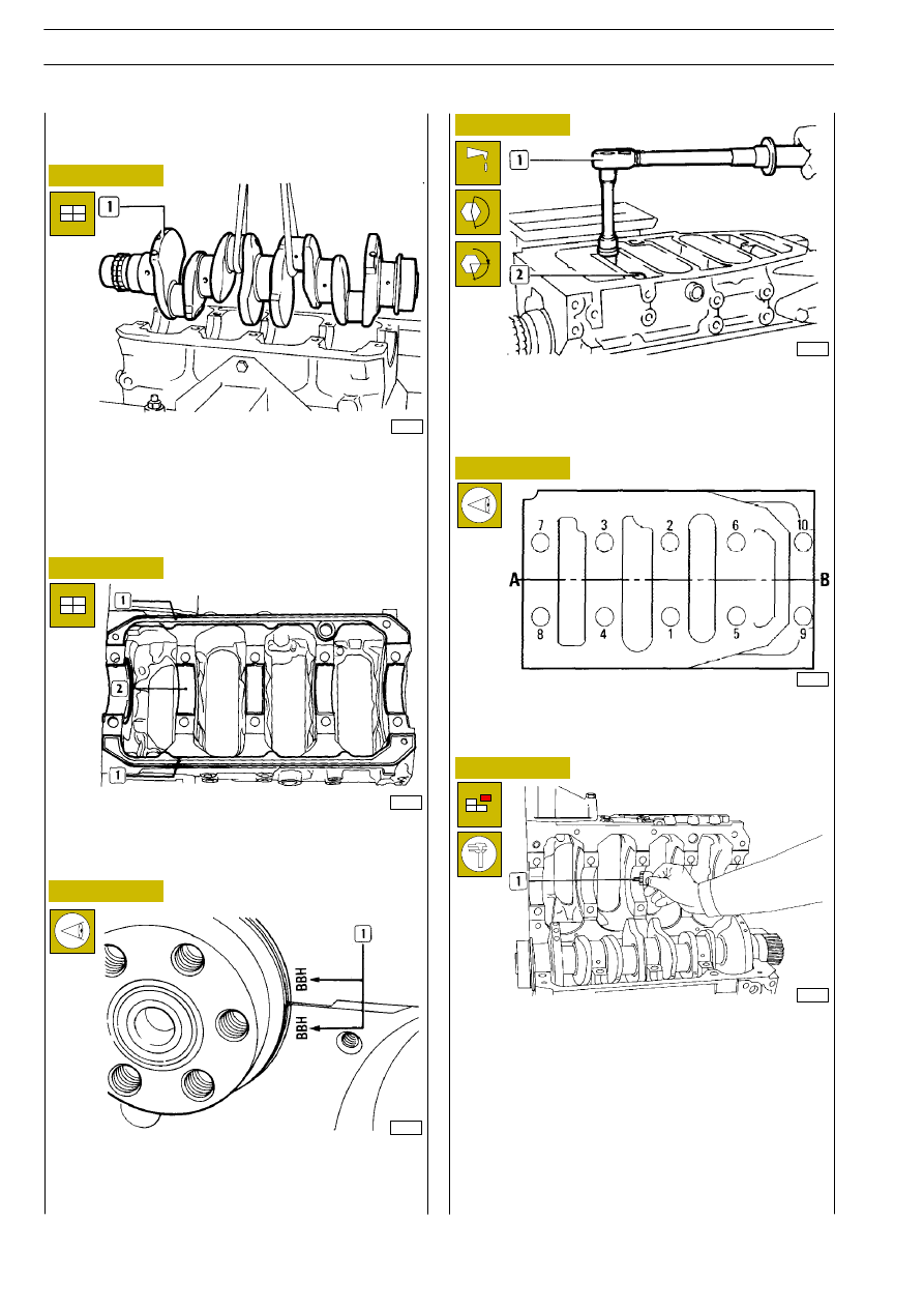
- Set rubber sealing gaskets (1) and small end bearings (2)

on lower crankcase.

- Fit the lower crankcase on the upper crankcase, verifying

that reference marks (1) correspond, since the parts
component crank- case are not interchangeable.

- Screw and tighten screws (2) according to the following

two stages:

- 1st stage: by torque wrench, to 50

± 5 Nm;

- 2nd stage: 90º

± 5º angle tightening according to the

following diagram.

A. Valve gear side - B. Flywheel side

Tightening order diagram of lower/upper crankcase fastening
screws.

- Dismantle lower crankcase.

The clearance between small end bearings is calculated by
comparing the width the calibrated wire has reached, in the
point of greater deflection, with the scale graduation
indicated on the envelope containing the calibrated wire.
The numbers indicated on the scale indicate the coupling
clearance, in millimetres, that must be of 0.032

÷ 0.102 mm.

If a clearance different than that specified is found, replace half
bearings and repeat the check; once the prescribed clearance
is obtained, lubricate small end bearings and fit lower
crankcase definitively, tightening fastening screws as
described previously.

Fit crankshaft (1).
Check the clearance between crankshaft main journals and
respective bearings, proceeding as follows:

- clean carefully the journals;

- apply a calibrated wire on main journals.

540811

Measuring main journals assembly
clearances

α

ENGINES 8140.43R/B/S/N

70

D

AILY

Base - May 2004

Trim any gasket excess in the points indicated by the arrows.
Lubricate crankshaft (1) shank. Fit rear gasket (3) and tighten
screws to specified torque. Remove chock (2).

540440

Front crankshaft cover

18519

Figure 83

End float check is carried out by placing a magnetic-base dial
gauge (1) on crankshaft (2), as shown in the figure; the normal
assembly clearance is of 0.060-0.310 mm.
If a greater clearance is found replace rear small end thrust
bearings and repeat float check between crankshaft pins and
small end bearings.

Checking crankshaft end float

Figure 84

Figure 85

Figure 86

540460

Rear crankshaft cover

Checking alignment pulley crankshaft

50669

46668

Cut the exceeding seal in the point shown by arrows.
Lubricate drive shaft shank. Fit front cover (1) and tighten
fixing screws (3) to the specified torque. Remove chock (2).

Push the crankshaft (1) towards the flywheel side so as to
keep the crankshaft end in contact with the thrust bearing.
In these conditions, measure the distance X between the
crankcase (3) and the end of the gear (2). If the distance X
is 53.82

÷ 54.55 , it is necessary to place a spacer n 98428488

(5) (thickness 0.5

± 0.05 mm) between the gear (2) and the

pulley (4 or 6). If the distance X is 54.56

÷ 55.12, don’t apply

the spacer.
Mount the pulley (4), (engine without air-conditioner
compressor)

or

(6),

(engine

with

air-conditioner

compressor).
Measure the distance Y or Y

1

between the end of the pulley

(4 or 6) and the crankcase at the two extreme positions of
crankshaft end float.

Y = 89.67

÷ 91.03 mm

Y

1

= 107.17

÷ 108.53 mm

45068

The rear (3) and front (1, Figure 86) covers of the
crankshaft have the “ROTOSTAT” type gasket
integrated.
The covers are supplied as spare parts together
with the chock (2). The chock (2) must not be
removed from the gasket until this has been fitted
on the crankshaft.
In addition, the thickness of the cover is not the
same as that of the first assembly.
This is to prevent its lip from getting onto the shank
of the crankshaft in exactly the same position where
it could be worn.

NOTE

The remaining fixing screws should be mounted
after positioning the belt guard.

NOTE

ENGINES 8140.43R/B/S/N

71

D

AILY

Base - May 2004

Gearbox input shaft supporting bearing (3) dismantling and
refitting is carried out by means of a common punch.

Make sure there are no blisters, cuts or damage of any kind
anywhere on the surface of the flywheel (1) shown by the
arrow, otherwise replace flywheel.
Check clutch disk bearing surface. If it shows any scoring it is
necessary to lathe-shape it.

540853

Replacing engine flywheel ring gear

Check the state of the teeth of the ring gear (2). If any teeth
are broken or excessively worn, remove it from the flywheel
(1) with a general-purpose punch and fit the new one, after
heating it to a temperature of 150ºC for 15

÷ 20 min. The

bevel, made on the internal diameter of the ring, must be
facing towards the flywheel.

41098

Remove piston (1) from connecting rod by removing split
ring (2) and extracting pin (3).

50671

CONNECTING ROD - PISTON ASSEMBLY

1. Piston - 2. Pin - 3. Split ring - 4. Sealing ring -

5. Oil scraper ring - 6. Slotted oil scraper ring with spiral

spring - 7. Connecting rod body - 8. Half bearings -

9. Connecting rod cap - 10. Cap fastening screws.

Check pistons: they must not show any trace of seizing,
scoring, cracks or excessive wear, otherwise replace them.

50670

Figure 87

Figure 88

Figure 89

Figure 90

41132

Fit engine flywheel (1) without tightening fixing screws (2).

For final screw (2) tightening see chapter ”Flywheel setting”.

Figure 91

5408

CONNECTING ROD - PISTON AS-
SEMBLY

41097

Remove split rings (1) from piston (2) with pliers 99360183
(3).

540852

Replacing bearing supporting gear-
box input shaft

Flywheel rated thickness is 53 mm.

NOTE

Before reusing flywheel fastening screws verify with
a micrometer that threading diameter of the
screws is not less than 10.8 mm in any point,
otherwise replace them.

NOTE

ENGINES 8140.43R/B/S/N

72

D

AILY

Base - May 2004

ENGINE FLYWHEEL

60’

74944

74945

Figure 92

Figure 93

MAIN DATA FOR KS PISTON, PINS AND PISTON RINGS - ENGINES 8140.43B/R

*Measured on the diameter of 91.4 mm.

MAIN DATA FOR MONDIAL PISTON, PINS AND PISTON RINGS - ENGINES 8140.43B/R

*Measured on the diameter of 91.4 mm.

Figure 94

74946

MAIN DATA ON KS - MONDIAL PISTONS, PINS AND SPRING RINGS -

ENGINES 8140.43N/S

*Measured on the diameter of 91.4 mm.

60’

60’

ENGINES 8140.43R/B/S/N

73

D

AILY

Base - May 2004


Content   ..  20  21  22  23   ..