Iveco Daily. Manual - part 25


  Index      Iveco     Iveco Daily - service repair manual 2004 year


Search            


Content   ..  23  24  25  26   ..


Iveco Daily. Manual - part 25


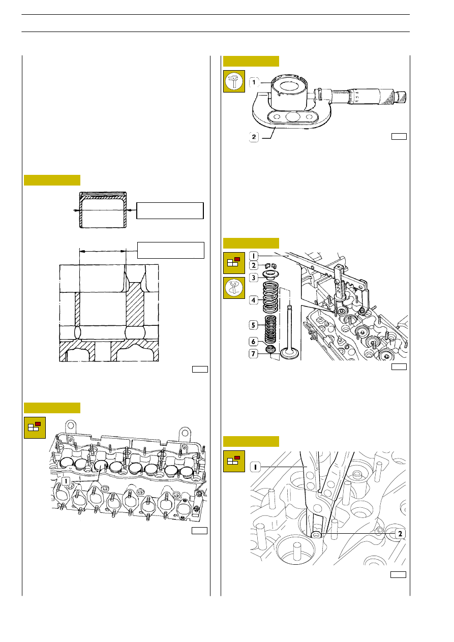
Check valve tappet (1) diameter, with a micrometer (2) and
with an inside micrometer gauge the diameter of relevant
seats on cylinder head; they must be equal to those indicated
in Figure 125. The normal fitting clearance between the
maximum diameter of valve tappet and that of seats is
0.030

÷ 0.075 mm.

The replacement of valve tappet, because of an excessive
clearance in the seats, requires to fit oversized valve tappet
after boring the seats by means of a suitable reamer.

540662

Disassembling valves

41113

Valve dismantling is performed with tool 99360268 (1) by
exerting a pressure on cap (3) so that, pressing springs (4 and
5) it is allowed to remove lock cones (2). Then remove:
upper cap (3), springs (4 and 5) and lower cap (6).
Repeat operation on all valves.
Overturn cylinder head and remove valves (7).

25227

MAIN DATA ON VALVE TAPPET AND RELEVANT

SEAT ON CYLINDER HEAD

43,950

÷ 43,970

44,000

÷ 44,025

Figure 125

Figure 126

Figure 127

Figure 128

Figure 129

541211

Checking cam lift and journal align-
ment

Set shaft on centres and check, with a centesimal dial gauge
placed on central support, that alignment error is no greater
than 0.04 mm, otherwise replace shaft. Also check cams lift:
it should be 10.5 mm for those of outlet and 9.5 mm for
those of inlet; if different values are found replace the shaft.

18877

Extract valve tappet (1) complete with adjusting caps, placing
them in a container according to the order they were when
removed.
Lateral surface of valve tappet must be very smooth and dent
free.
Small dents can be eliminated with a very fine abrasive stone.

18891

Using suitable pliers (1), remove the seal rings (2) from the
valve guides.

50674

541224

VALVE TAPPET

ENGINES 8140.43R/B/S/N

82

D

AILY

Base - May 2004

Check for hydraulic leak by means of suitable equipment
(1-2-3-4).
Supply water, through pump, heated at

~ 90°C and at 2 ÷ 3

bar pressure.
Should plug leaks be found, replace them using a proper
beater for removal/refitting.

MAIN DATA ON INTAKE AND EXHAUST VALES AND

VALVE GUIDES

18542

18879

41115

18625

Figure 130

Figure 131

Figure 132

Figure 133

Figure 134

The check of mating surface of the head (1) to cylinder group
is performed by means of a rule (2) and a thickness gauge (3).
If a deformation is found, measure cylinder head thickness,
whose rated value is 150

± 0.1 mm.

When checking, if the amount of material to be removed for
flattening cylinder head is greater than 0.4 mm, replace
cylinder head.

Remove any carbonic deposits on valves, using the special
metal brush.
Check that valves do not show any trace of seizure, crack or
burning. Regrind seats on valves, if necessary, with grinder
99301014, removing an amount of material, as little as
possible.

Checking cylinder head seal

Checking cylinder head mating surface

540662

VALVES

Removing

deposits,

refacing

and

checking

valves

INTAKE

EXHAUST

If there is any leakage from the cylinder head, it must be
replaced.

18882

With a micrometer (2) measure valve stem (1): it must be
7.985

÷ 8.00 mm.

Before mounting the plugs, apply water-reacting
sealant on their sealing surfaces.

NOTE

ENGINES 8140.43R/B/S/N

83

D

AILY

Base - May 2004

These checks are carried out with a magnetic-base dial gauge
(1) set as shown. Assembly clearance is 0.023

÷ 0.053 mm.

On emptying valve (2) check that centring error is not
greater than 0.03 mm.

Once valve guides are driven, sleek them with smoothing
tool 99390310 (1).

41842

Figure 135

Figure 136

Figure 137

Figure 138

Figure 139

Figure 140

Checking clearance between valve stem and
valve guide and centring valves

Remove valve guide with punch 99360288 (1).

18883

18885

Heat cylinder head to 80

° ÷ 100°C and with punch

99360288 (1) equipped with part 99360291 (2) fit new valve
guide (3) previously cooled in liquid nitrogen.

41116

Valve guide fitting.

18886

Check valve seats (2). If any slight scoring or burning is found
regrind them with tool HUNGER 99360419 (1) according to
inclination values specified in Figure 141.
If it is required to replace them, using the same tool and taking
care not to damage the cylinder head, remove as much
material as possible from valve seats, until it is possible to
extract them from the cylinder head with a punch.

18887

540667

VALVE GUIDES

Replacing valve guides

Reaming valve guides

540661

VALVE SEATS

Regrinding and replacing valve seats

ENGINES 8140.43R/B/S/N

84

D

AILY

Base - May 2004

Fit valves and injectors.
Check valve sealing and respective seats with tools (1-2).

18888

18890

Figure 141

Figure 142

Figure 143

Figure 144

MAIN DATA ON VALVE SEATS

Heat cylinder head to 80

° ÷ 100°C and, by means of a

suitable punch (1), fit in it the new valve seats (2), previously
cooled in liquid nitrogen.
With tool HUNGER 99360419, regrind valve seats according
to inclination values specified in Figure 141.

Clean injector seats from any deposit, using cutter 99394038
(1).

Figure 145

50675

1

2

18880

With dial gauge (1) check that, from cylinder head surface,
the hollow of valves and injector (2) protrusion have the
prescribed value.

1

2

18889

EXHAUST

INTAKE

REFERENCE 34.8

REFERENCE 39.7

3.6

÷

3.7

10.5

÷

10.45

ENGINES 8140.43R/B/S/N

85

D

AILY

Base - May 2004


Content   ..  23  24  25  26   ..