Engines Iveco C87 / Cursor 87. Manual - part 30


  Index      Iveco     Engines Iveco C87 / Cursor 87 (CURSOR TIER 3 SERIES) - service repair manual 2007 year


Search            


Content   ..  28  29  30  31   ..


Engines Iveco C87 / Cursor 87. Manual - part 30


Install the connecting rod caps (1) with half-bearings; tighten
the connecting rod cap fixing screws (2) to 50 Nm (5 kgm)
torque. By tool 99395216 (3), tighten the screws further at
90

° angle.

Remove the caps and check the clearance by comparing the
width of the calibrated wire with the scale calibration on the
envelope containing the wire.

540610

CYLINDER HEAD

Before dismounting cylinder head, check cylinder head for
hydraulic seal by proper tooling; in case of leaks not caused
by cup plugs or threaded plugs, replace cylinder head.

115886

47583

36159

Figure 62

Figure 63

Figure 64

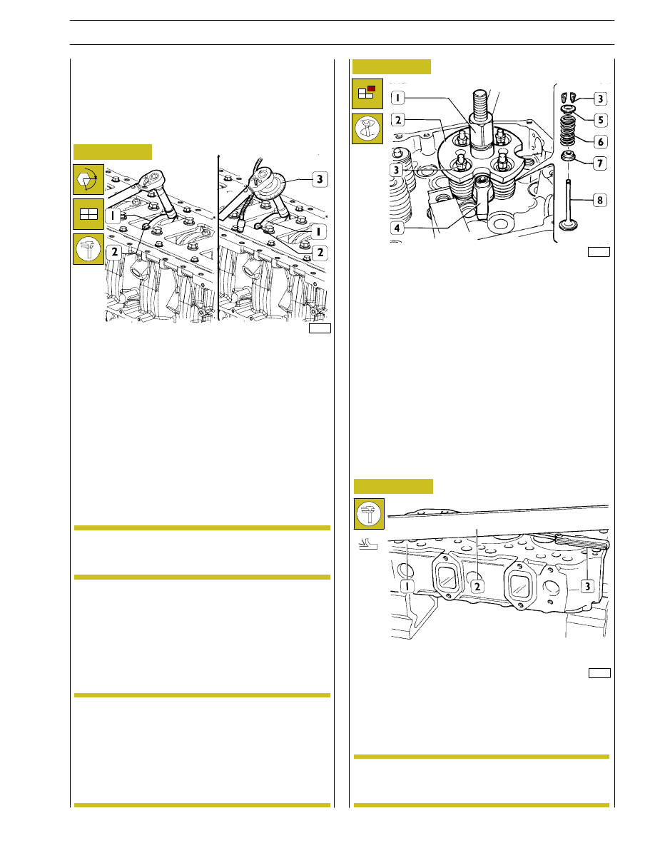
Install and fix tool 99360264 (2) with bracket (4); tighten by
lever (1) until cotters are removed (3); remove the tool (2)
and the upper plate (5), the spring (6) and the lower plate (7).

Repeat the operation on all the valves.

Turn the cylinder head upside down and remove the valves
(8).

The planarity (1) is checked using a ruler (2) and a thikness
gauge (3). If deformations exist, surface the head using proper
surface grinder; the maximum amount of material to be
removed is 0.2 mm.

To check the clearance proceed as follows:

connect the connecting rods to the relative main journals,
place a length of calibrated wire on the latter.

α

Checking the planarity of the head on the
cylinder block

(Demonstration)

After leveling, make sure that valve sinking and
injector protrusion are as described in the relative
paragraph.

540831

Checking assembly clearance of big
end pins

In case of plugs dismounting/replacement, on
mounting, apply sealant Loctite 270 on plugs.

NOTE

Dismounting the valves

Before dismounting cylinder head valves, number
them in view of their remounting in the position
observed on dismounting should they not have to
be overhauled or replaced.

Intake valves are different form exhaust valves in
that they have a notch placed at valve head centre.

NOTE

NOTE

SECTION 4 - OVERHAUL AND TECHNICAL SPECIFICATIONS

35

F2C CURSOR ENGINES

MAIN DATA - VALVES AND VALVE GUIDES

* Values to be obtained after installing the valve guides

92841

47509

Figure 65

Figure 66

Check, by means of a micrometer, that valve stem diameters
are as specified; if necessary, grind the valves seat with a
grinder, removing the minimum quantity of material.

INSTALLATION DIAGRAM FOR VALVE GUIDES AND VALVES

* Values to be obtained after installing the guide valves

540667

VALVE GUIDES

*

Figure 67

48625

540622

VALVE

Removing deposits and checking the valves

Remove carbon deposits using the metal brush supplied.
Check that the valves show no signs of seizure or cracking.

Check the diameter of the valve stem using a micrometer
(see Figure 66) and replace if necessary.

36

SECTION 4 - OVERHAUL AND TECHNICAL SPECIFICATIONS

F2C CURSOR ENGINES

Base - June 2007

41032

115887

Figure 68

Figure 69

Remove valve guides by means of tool 99360288.

Install by means of tool 99360288 equipped with part
99360294, which determines the exact installation position
of valve guides into the cylinder heads; if they are not
available, install the valve guides in the cylinder head so that
they project out by mm 16.3 to 16.7 (Figure 66).

After installing the valve guides, smooth their holes with
sleeker 99390310.

Ream the valve seats (2) on cylinder head using tool (1).

After reaming the valve seats, use tool 99370415, to make
sure that the valve position, with respect to the cylinder head
surface, is the following:

- -0.5 to -0.8 mm (recessing) of exhaust valves;

- -1.6 to 1.9 mm (recessing) of discharge valves.

To replace the injector case (2), act as follows:

- thread the case (2) with tool 99390804 (1).

Carry out operations described in the following figs. by
fixing tools to the cylinder head by means of braket A.

Replacing of valve guides

Replacing - Reaming the valve seats

To replace the valve seats, remove them using the
appropriate tool.

Valve seats must be reamed whenever valves or
valve guides are replaced or ground.

NOTE

540613

REPLACING INJECTOR HOLDER
CASES

Removal

SECTION 4 - OVERHAUL AND TECHNICAL SPECIFICATIONS

37

F2C CURSOR ENGINES

45633

Figure 70

Figure 71

Figure 72

- Remove any residue (1), with tool 99390772 (2), from

the cylinder head groove.

1

2

- fasten extractor 99342149 (2) to case (3), by tightening

the nut (1), and pull out the case from cylinder head.

115888

115889

- Lubricate sealing rings (3) and fit them to the case (4);

fix tool 99360554 (2) to the cylinder head by means of
bracket A, install the new case, tighten the screw (1),
upsetting the case lower part.

115890

Figure 73

- Adjust the casing hole (3) with borer 99394043 (1) and

guide bushing 99394045 (2).

38

SECTION 4 - OVERHAUL AND TECHNICAL SPECIFICATIONS

F2C CURSOR ENGINES

Base - June 2007


Content   ..  28  29  30  31   ..