Isuzu D-Max / Isuzu Rodeo (TFR/TFS). Manual - part 558


  Index      Ford     Isuzu D-Max / Isuzu Rodeo TFR/TFS series - service repair manual 1997-2003 year


Search            


Content   ..  556  557  558  559   ..


Isuzu D-Max / Isuzu Rodeo (TFR/TFS). Manual - part 558


6A – 70  ENGINE MECHANICAL 
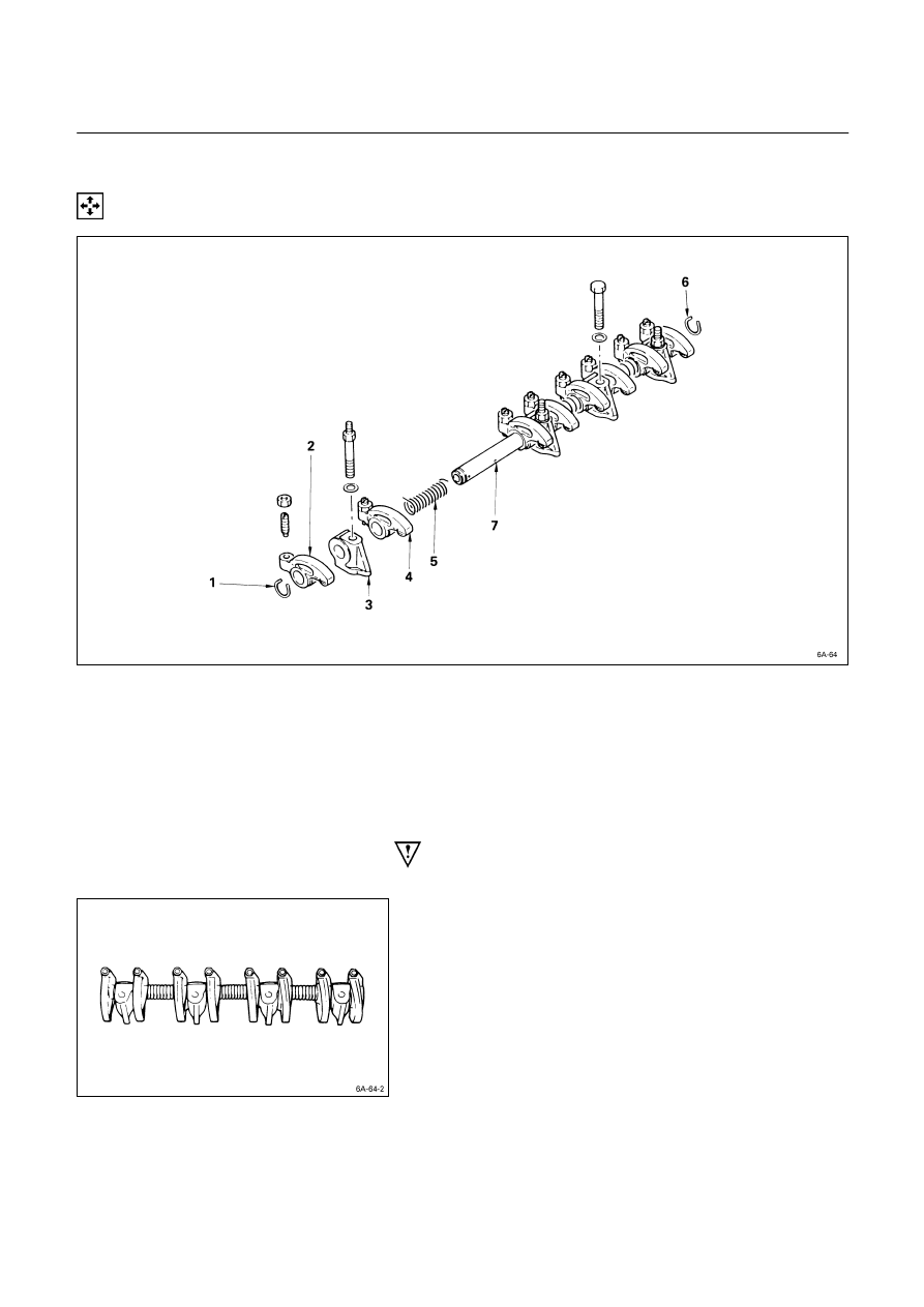
 

MINOR COMPONENTS 

 ROCKER ARM SHAFT AND ROCKER ARM 


Disassembly Steps 


J

 1. Rocker arm shaft snap ring 


5. 

Rocker arm shaft spring 


J

 2. Rocker arm 


6. 

Rocker arm shaft snap ring 


J

 3. Rocker arm shaft bracket 


7. 

Rocker arm shaft 

   4. 

Rocker 

arm 


Important Operations 


1.  Rocker Arm Shaft Snap Ring 
2. Rocker 

Arm 

3.  Rocker Arm Shaft Bracket 

1)  Use a pair of pliers to remove the snap rings. 
2)  Remove the rocker arms. 
3)  Remove the rocker arm shaft brackets. 

If the rocker arms and rocker arm shaft brackets are 
to be reinstalled, mark their installation positions by 
tagging each rocker arm and rocker arm shaft bracket 
with the cylinder number from which it was removed. 


ENGINE MECHANICAL   6A – 71 

 CYLINDER HEAD 


Disassembly Steps 


   1. 

Intake manifold 


J

 6. 

Intake and exhaust valve 

   2. 

Intake manifold gasket 


7. 

Valve stem oil seal 


J

 3. 

Split collar 


8. 

Valve spring lower seat 

   4. 

Valve spring upper seat 


9. 

Cylinder head 

   5. 

Valve spring 


6A – 72  ENGINE MECHANICAL 


Important Operations 


3. Split 

Collar 

1)  Place the cylinder head on a flat wooden surface. 
2)  Use the spring compressor to remove the split collars.

Do not allow the valve to fall from the cylinder head. 
Spring Compressor: 9-8523-1423-0 (J-29760) 


6.  Intake and Exhaust Valve 

If the intake and exhaust valves are to be reinstalled, mark 
their installation positions by tagging each valve with the 
cylinder number from which it was removed. 
If the intake and exhaust valves are to be replaced, the 
valve guides must also be replaced. 

ENGINE MECHANICAL   6A – 73 


 PISTON AND CONNECTING ROD 


Disassembly Steps 


J

 1. 

Connecting rod bearing 


J

 4. 

Piston pin 


J

 2. 

Piston ring 


5. 

Connecting rod 


J

 3. 

Piston pin snap ring 


J

 6. 

Piston 

015L200002


For 4JA1/4JA1T/4JA1TC 
/4JH1TC only


Content   ..  556  557  558  559   ..