Isuzu D-Max / Isuzu Rodeo (TFR/TFS). Manual - part 299
AUTOMATIC TRANSMISSION (AW30-40LE) 7A-45
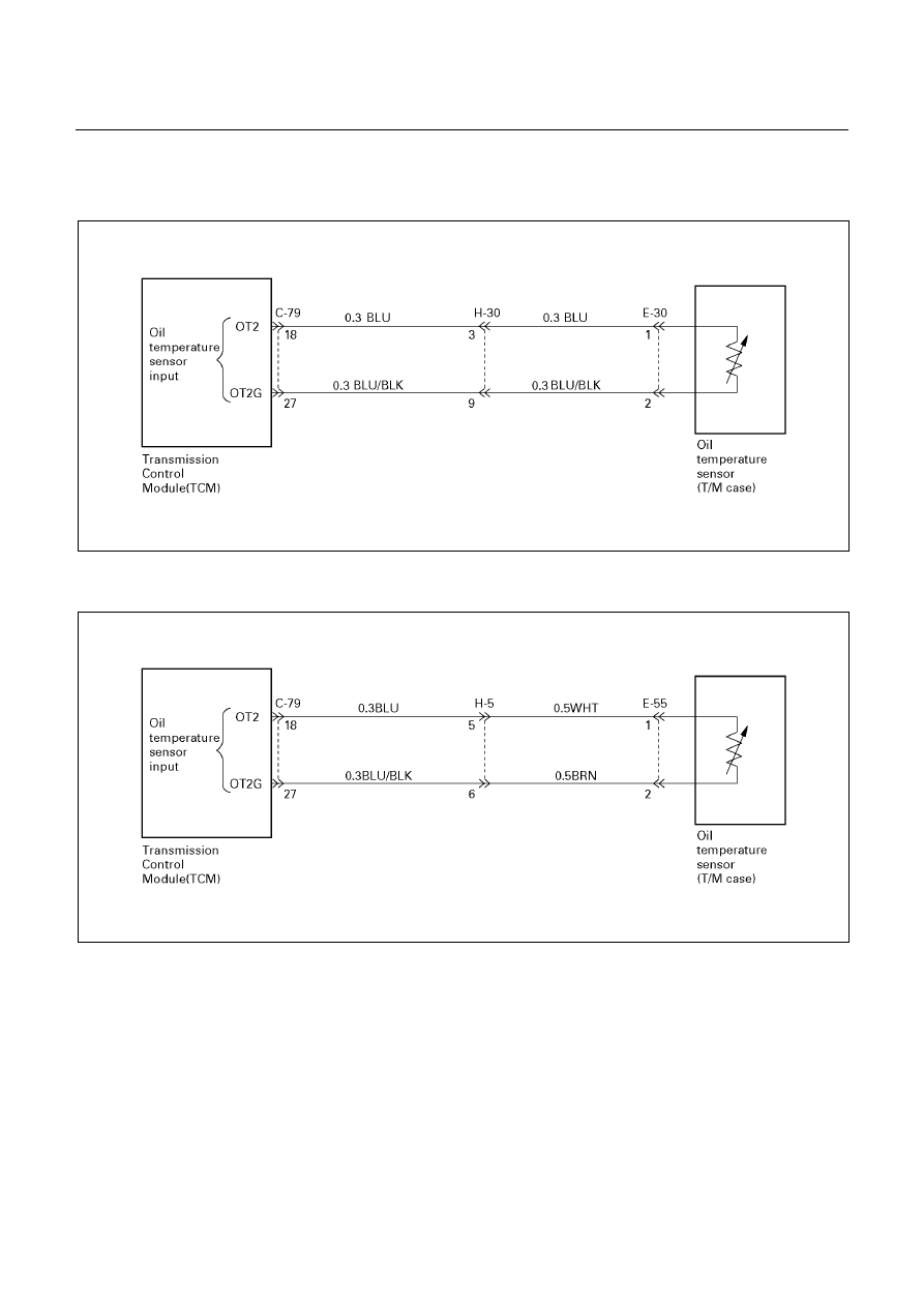
DTC P0710 (FLASHING CODE 16)
OIL TEMPERATURE SENSOR FAILURE (OT2)
UBS (For General Export)
D07R200058
TFR/S (For Australia) and TFR (For South Africa)
D07L200003