Isuzu D-Max / Isuzu Rodeo (TFR/TFS). Manual - part 231


  Index      Ford     Isuzu D-Max / Isuzu Rodeo TFR/TFS series - service repair manual 1997-2003 year


Search            


Content   ..  229  230  231  232   ..


Isuzu D-Max / Isuzu Rodeo (TFR/TFS). Manual - part 231


ENGINE DRIVEABILITY AND EMISSIONS

6E–165

10

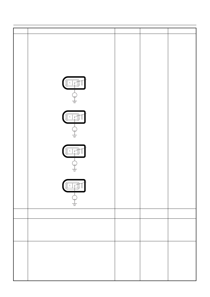
Using the DVM and check the injector signal circuit.

1. Ignition “On”, engine “Off”. 

2. Disconnect the injector connector for the affected

cylinder. 

3. Check the circuit for short to battery voltage

circuit. 

Was the DVM indicated battery voltage?

Repair faulty 

harness and 

verify repair

Go to Step 12

11

Replace the injector for the affected cylinder. 
Was the problem solved?

Verify repair

Go to Step 12

12

Is the ECM programmed with the latest software
release? 
If not, download the latest software to the ECM using
the “SPS (Service Programming System)”. 
Was the problem solved?

Verify repair

Go to Step 13

13

Replace the ECM. 
Is the action complete? 
IMPORTANT:  The replacement ECM must be
programmed. Refer to section of the Service
Programming System (SPS) in this manual. 
Following ECM programming, the immobiliser system
(if equipped) must be linked to the ECM. Refer to
section 11 “Immobiliser System-ECM replacement” for
the ECM/Immobiliser linking procedure.

Verify repair

Step

Action

Value(s)

Yes

No

V

2

E-6

No.1 Cylinder

V

2

E-7

No.2 Cylinder

V

2

E-8

No.3 Cylinder

V

2

E-9

No.4 Cylinder

6E–166

ENGINE DRIVEABILITY AND EMISSIONS

DIAGNOSTIC TROUBLE CODE (DTC) P0325 KNOCK SENSOR (KS) CIRCUIT 

MALFUNCTION

Condition for setting the DTC and action taken when the DTC sets

Circuit Description

The knock sensor (KS) system is used to detect engine
detonation. The knock sensor produced an AC voltage
signal. The knock sensor sends this signal to the ECM.
The amplitude and the frequency of the AC voltage
signal depends upon the knock level being detected.
The ECM will then retard the spark timing based on the

signals from the Knock Sensor.

Diagnostic Aids

Correct any abnormal engine noise before using the
diagnostic table.
Check for an open circuit.

Diagnostic Trouble Code (DTC) P0325 Knock Sensor Module Circuit

Code

Type

DTC Name

DTC Setting Condition

Fail-Safe (Back Up)

P0325

B

Knock Sensor Module Circuit

1. No DTC relating to MAP sensor. 
2. Engine coolant temperature is more than 

50°C. 

3. Engine speed is more than 1600rpm. 
4. Knock sensor filter module integrated cir-

cuit malfunction.

ECM retards ignition timing 4°C.

µP

0.5
GRY

J1-27

+5V

µP

µP

5Volts
Reference

Knock
Sensor

0.5
YEL

0.5
WHT/
BLU

J1-7

0.5
BLU/
PNK

J1-32

0.5
BLK/
YEL

J1-15

J1-3

Engine
Coolant
Temperature(ECT)
                   Sensor

Throttle
Position Sensor

Knock Filter
Module

Engine
Control
Module
(ECM)

Step

Action

Value(s)

Yes

No

1

Was  the  “On-Board Diagnostic (OBD) System Check”
performed?

Go to Step 2

Go to On Board 

Diagnostic 

(OBD) System 

Check

ENGINE DRIVEABILITY AND EMISSIONS

6E–167

2

1. Connect the Tech 2. 

2. Review and record the failure information. 

3. Select  “F0: Read DTC Infor By Priority” in “F0:

Diagnostic Trouble Code”. 

Is the DTC P0325 stored as “Present Failure”?

Go to Step 3

Refer to 

Diagnostic Aids 

and Go to Step 

3

3

1. Using the Tech2, ignition “On” and engine “Off”. 

2. Select “Clear DTC Information” with the Tech2 and

clear the DTC information. 

3. Operate the vehicle and monitor the “F5: Failed

This Ignition” in “F2: DTC Information”.

Was the DTC P0325 stored in this ignition cycle?

Go to Step 4

Refer to 

Diagnostic Aids 

and Go to Step 

4

4

Check for poor/faulty connection at the knock sensor
or ECM connector. If a poor/faulty connection is found,
repair as necessary. 
Was the problem found?

Verify repair

Go to Step 5

5

Visually check the knock sensor. 
Was the problem found? 

Go to Step 10

Go to Step 6

6

Listen to the engine noise while raising and lowering
the engine speed. 
Is a knock or audible noise present?

Go to Step 7

Go to Step 8

7

Repair the mechanical engine problem or a loose
bracket or component. 
Is the action complete?

Verify repair

Step

Action

Value(s)

Yes

No

32

3

E-60(J1)

E-84

6E–168

ENGINE DRIVEABILITY AND EMISSIONS

8

Using the DVM and check the knock sensor circuit.
Breaker box is available: 

1. Ignition “Off”, engine “Off”. 

2. Install the breaker box as type A. (ECM

disconnected) Ref. 6E-80.

3. Disconnect the knock sensor. 

4. Check the circuit for open circuit. 

Was the problem found?

Breaker box is not available: 

1. Ignition “Off”, engine “Off”. 

2. Disconnect the knock sensor connector and ECM

connector. 

3. Check the circuit for open circuit. 

Was the problem found?

Repair faulty 

harness and 

verify repair

Go to Step 9

9

Substitute a known good knock sensor and recheck.
Was the problem solved?

Go to Step 10

Go to Step 11

10

Replace the knock sensor. 
Was the problem solved?

Verify repair

Go to Step 11

11

Is the ECM programmed with the latest software
release? 
If not, download the latest software to the ECM using
the “SPS (Service Programming System)”. 
Was the problem solved?

Verify repair

Go to Step 12

12

Replace the ECM. 
Is the action complete? 
IMPORTANT:  The replacement ECM must be
programmed. Refer to section of the Service
Programming System (SPS) in this manual. 
Following ECM programming, the immobiliser system
(if equipped) must be linked to the ECM. Refer to
section 11 “Immobiliser System-ECM replacement” for
the ECM/Immobiliser linking procedure.

Verify repair

Step

Action

Value(s)

Yes

No

3

32

E-84

2

1

3

E-60(J1)

E-84

32

2

1


Content   ..  229  230  231  232   ..