Isuzu D-Max / Isuzu Rodeo (TFR/TFS). Manual - part 1840


  Index      Ford     Isuzu D-Max / Isuzu Rodeo TFR/TFS series - service repair manual 1997-2003 year


Search            


Content   ..  1838  1839  1840  1841   ..


Isuzu D-Max / Isuzu Rodeo (TFR/TFS). Manual - part 1840


7A1-22  CONSTRUCTION AND FUNCTION
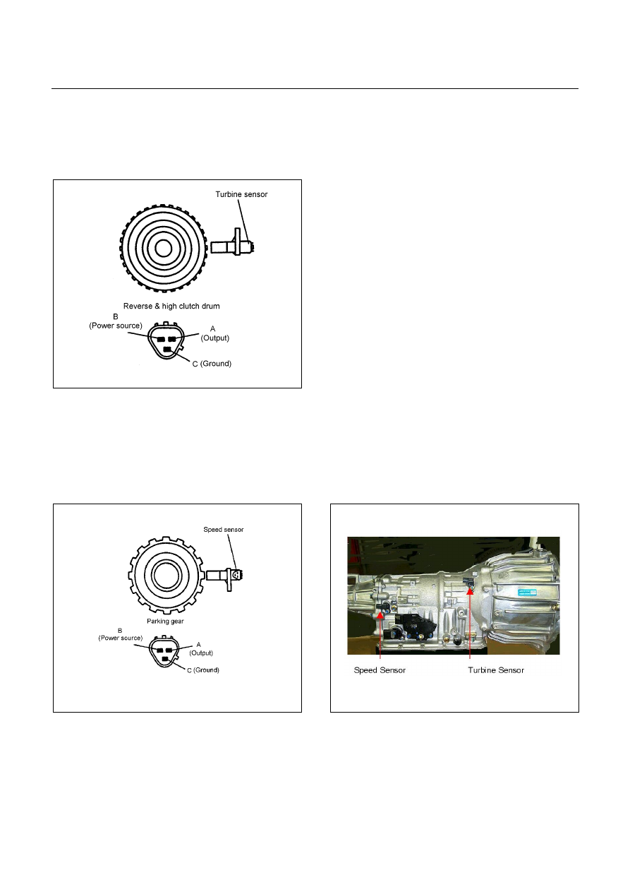
 

TURBINE SENSOR 

 The turbine sensor is a hall element.  It is installed to the front of the transmission case.  The turbine 

sensor converts the rotations of the reverse & high clutch drum fitted with the input shaft by spline to 
pulse signal and sends the signal to TCM. 

 One turn of the reverse & high clutch drum generates 32-pulse signal, which is sent to the TCM. 


Figure 38. Turbine Sensor


SPEED SENSOR 

 The speed sensor is a hall element.  It is installed to the rear of the transmission case.  The speed sensor 

converts the rotations of the parking gear fitted with the output shaft by spline to a pulse signal which is 
sent to the TCM. 

 One turn of the parking gear generates a 16-pulse signal to be sent to the TCM. 


Figure 39. Speed Sensor


Figure 40. Location of Turbine & Speed Sensor


CONSTRUCTION AND FUNCTION  7A1-23


THROTTLE POSITION SENSOR (TPS) 

 Opening of the accelerator pedal is converted to an electric signal which is transmitted from ECM to TCM. 


Figure 41. Throttle Position Sensor


Figure 42. Pin Assignment


ENGINE SPEED SENSOR (=TDC SENSOR) 

 The engine speed sensor converts the crankshaft from the TDC (Top Dead Center) sensor rotation to a 

pulse signal which is transmitted from ECM to TCM.


 Ground 

 Signal 

 Shield Line

Figure 43. TDC Sensor


Figure 44. Pin Assignment


7A1-24  CONSTRUCTION AND FUNCTION


BRAKE SWITCH 

 The brake switch is installed to the brake pedal.  When the driver steps on the brake pedal, an electric 

signal is sent to the TCM.


Brake Switch

Accelerator Pedal 

Brake Pedal 


TCM A3 

+12V 

Figure 45. Brake Switch


Figure 46. Pin Assignment


MODE SELECT SWITCH 

 The mode select switch is installed beside the select lever.  When the driver selects the PWR or 3rd, an 

electric signal is sent to the respectively.  It turns ON the indicator lamp in the meter.


 The 3rd START mode can be used only in the D range. 


Mode Select Switch 

Gear Select Lever 


Power 3rd 

Illumination 

Lamp 

1 (Illumination) 


2 (Ground) 


3 (TCM A24) 


4 (No Connection) 


5 (TCM A11) 


6 (Ground) 


2

6

5

Figure 47. Mode Select Switch


Figure 48. Pin Assignment


CONSTRUCTION AND FUNCTION  7A1-25


TRANSMISSION CONTROL MODULE (TCM) 

 The TCM is fitted side of brake pedal by means of two stud bolts. 

 The TCM judges necessary line pressure, gear shifting point and lock-up operation based on electrical 

signals from switches and sensors and sends appropriate signals to solenoids. 


Connect to White Connector                       Connect to Grey Connector


Figure 49. Pin Assignment


Pin No. 

Pin Assignment 

Pin No.

Pin Assignment 

B1 

2-4 Brake Oil Pressure Switch 

A1 

V BATT (Battery Back-up Power Supply)


B2 

2 Range Switch 

A2 

P Range Switch 

B3 

Turbine Sensor  

A3 

Brake Switch 

B4 

ATF Thermo Sensor 

A4 

3rd Start Indicator Lamp 

B5 

Ground 

A5 

K-Line Signal (Tech 2 Serial Communication) 

B6 

Low & Reverse Brake Duty Solenoid 

A6 

No Connection 

B7 

2-4 Brake Duty Solenoid  

A7 

Engine Speed Sensor 

B8 

High Clutch Duty Solenoid 

A8 

No Connection 

B9 

Low Clutch Duty Solenoid 

A9 

No Connection 

B10 

N Range Switch 

A10 

Vehicle Speed Sensor Out (2WD Only) 

B11 

D Range Switch 

A11 

3rd START Select Switch 

B12 

Low & Reverse Brake Oil Pressure Switch 

A12 

4L Mode Switch (4WD Only) 

B13 

Vehicle Speed Sensor 

A13 

No Connection 

B14 

ATF Thermo Sensor Ground 

A14 

No Connection 

B15 

Ground 

A15 

No Connection 

B16 

No Connection 

A16 

Throttle Position Sensor 

B17 

Lock-up Duty Solenoid 

A17 

3 Range Switch 

B18 

Vign 

Ignition Power Supply) 

A18 

DIAG Switch (Test Switch) 

B19 

R Range Switch 

A19 

A/T OIL TEMP Indicator Lamp 

B20 

High Clutch Oil Pressure Switch 

A20 

CHECK TRANS Indicator Lamp 

B21 

L Range Switch 

A21 

POWER DRIVE Indicator Lamp 

B22 

Ground (Shift Solenoid) 

A22 

No Connection 

B23 

Line Pressure Solenoid  

A23 

No Connection 

B24 

Vign (Ignition Power Supply) 

A24 

POWER DRIVE Select Switch 


Content   ..  1838  1839  1840  1841   ..