Isuzu D-Max / Isuzu Rodeo (TFR/TFS). Manual - part 1792


  Index      Ford     Isuzu D-Max / Isuzu Rodeo TFR/TFS series - service repair manual 1997-2003 year


Search            


Content   ..  1790  1791  1792  1793   ..


Isuzu D-Max / Isuzu Rodeo (TFR/TFS). Manual - part 1792


UNIT REPAIR (JR405E)  7A4-35 


08R&H36 


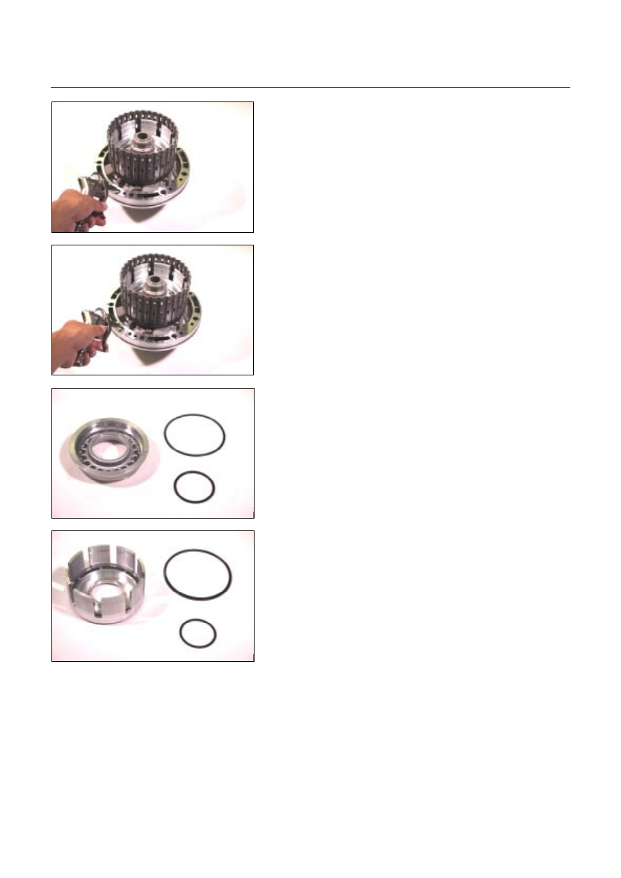
8.  High clutch piston 

9. Reverse clutch piston 

  Install the reverse and high clutch drum to the oil pump.

  Force compressed air into the oil pump oil channels. 

  Remove the high clutch piston and the reverse clutch 

piston. 


09R&H37 


12R&H39 


10.Seal ring (high clutch) 

Remove the 2 seal rings from the high clutch piston. 


13R&H38 


11.Seal ring (reverse clutch) 

Remove the 2 seal rings from the reverse clutch piston. 


Inspection 

Drive plate 

  Measure the drive plate facing thickness at 3 points. 

  Calculate the average value. 

If the average value is less than the specified limit, the 

drive plate must be replaced. 

Drive plate facing thickness:  

Standard – 2.0 mm (0.079 in) 

Limit – 1.8 mm (0.071 in) 


7A4-36  UNIT REPAIR (JR405E) 

Return spring 

  Check the number of effective return spring coils. 

If the number is less than the specified minimum, the 

return spring must be replaced. 
Effective return spring coils (standard): 10.2  

  Measure the return spring outside diameter, free length, 

and linear diameter. 

If any of the measured values exceed the specified limit, 

the return spring must be replaced. 

Return spring measurements (standard): 

Outside diameter – 8.0 mm (0.315 in) 

Free length – 27.1 mm (1.067 in) 

Linear diameter – 1.1 mm (0.043 in)  


10R&H40 


Reverse clutch piston 

  Apply compressed air (392 kPa/4.0 kg/cm

2

) to the

reverse clutch piston from the outside to the inside. 

The flow of air should be blocked. 


11R&H44 


  Apply compressed air (392 kPa/4.0 kg/cm

2

) to the 

reverse clutch piston from inside to the outside. 

The flow of air should be unrestricted. 


12R&H39 


Reassembly steps 

Coat the parts with ATF before installing them. 
1.  Seal ring (high clutch) 

Install new seal rings to the high clutch piston. 


UNIT REPAIR (JR405E)  7A4-37 


13R&H38 


2.  Seal ring (reverse clutch) 

Install new seal rings to the reverse clutch piston. 


14R&H32 


3. Reverse clutch piston 

Install the reverse clutch piston to the reverse and high 

clutch drum. 


15R&H31 


4.  High clutch piston 

Install the high clutch piston to the reverse clutch piston. 


16R&H33 


5. Return spring 

Install the return spring to the high clutch piston. 


17R&H30 


6.  High clutch cover 

  Carefully center the high clutch cover and install it. 

NOTE: 
If the clutch cover is not centered, the cover outside seal 
gum will be forced into the piston area where it will be 
damaged. 
 

7A4-38  UNIT REPAIR (JR405E) 


18R&H27 


7. Snap ring 

  Install the spring compressor to the reverse and high 

clutch drum. 

  Use the spring compressor to carefully force the high 

clutch cover down. 

Spring compressor: 5-8840-2767-0 

NOTE: 
To avoid damage to return springs, use only as much 
force as is required to press the high clutch cover into 
place. 


19R&H28 


  Install the new snap ring to the reverse and high clutch 

drum. 


20R&H25 


8. Dish plate, drive plates, driven plates, and retaining

plate 

Install the high clutch dish plate (1), the 5 driven plates (2), 

the 5 drive plates (3), and retaining plate (4). 


248L300002 


9. Snap ring 

Install the snap ring. 


Content   ..  1790  1791  1792  1793   ..