Isuzu D-Max / Isuzu Rodeo (TFR/TFS). Manual - part 1790


  Index      Ford     Isuzu D-Max / Isuzu Rodeo TFR/TFS series - service repair manual 1997-2003 year


Search            


Content   ..  1788  1789  1790  1791   ..


Isuzu D-Max / Isuzu Rodeo (TFR/TFS). Manual - part 1790


UNIT REPAIR (JR405E)  7A4-27 


Spring specifications 

No. Valve 

nomenclature 

Free length 

(mm / in) 

Outside 

diameter (mm 

/ in) 

Linear 

diameter (mm 

/ in) 

Number of 

coils 

14 

Pressure relief 

49.0 / 1.929 

7.6 / 0.299 

1.1 / 0.043 

17.3 

15 

Pressure regulator 

30.5 / 1.201 

14.0 / 0.551 

1.4 / 0.055 

5.7 

16 

Low and reverse brake fail (A) 

22.0 / 0.866 

7.0 / 0.276 

0.6 / 0.024 

10.0 

17 

Fail 

23.0 / 0.906 

11.0 / 0.433 

0.5 / 0.020 

13.2 

18 

Low and reverse brake amp 

19.5 / 0.768 

7.9 / 0.311 

0.5 / 0.020 

6.9 

19 2 

– 4 brake fail (A) 

24.8 / 0.976 

8.5 / 0.335 

0.9 / 0.035 

7.8 

20 

Low clutch amp (B) 

26.0 / 1.024 

11.0 / 0.433 

0.5 / 0.020 

6.9 

21 

Torque converter relief 

More than 47.2 

/ 1.858 

9.2 / 0.362 

1.6 / 0.063 

20.2 

22 2 

– 4 brake solenoid accumulator 

31.4 / 1.236 

9.8 / 0.386 

1.3 / 0.051 

9.3 

23 

High clutch accumulator 

51.0 / 2.008 

6.5 / 0.256 

0.8 / 0.031 

23.5 


Oil pressure switch 

Apply compressed air (392 kPa/4.0 kg/cm

2

) to the oil pressure 

switch to check the oil pressure switch continuity between the 
connector and screw. 


244L300011 


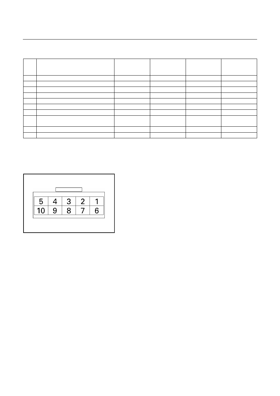
Oil temperature sensor (harness assembly) 

Check the oil temperature sensor resistance between harness 
terminals 7 and 6 (ground). 
 
Oil temperature sensor resistance: 2,400

∼2,600 ohms 

(20

℃) 


Solenoid 

Measure the resistance of each solenoid. 
 
Resistance: 
Brown connector – 3.0

∼∼∼∼

3.4 ohms (20

°°°°

C) 

Gray connector – 12.0

∼∼∼∼

13.2 ohms (20

°°°°

C) 

White connector – 12.2

∼∼∼∼

13.4 ohms (20

°°°°

C) 


Reassembly steps 

  Coat the parts with ATF before installing them. 

  Install the control valve to the control valve lower body.

  Install the oil filter to the control valve lower body. 


7A4-28  UNIT REPAIR (JR405E) 


OIL PUMP ASSEMBLY 


01PUMP32 

Legend 


1. Oil seal 


2. O-ring (small) 


3. Oil pump housing 

 4. 

Inner 

rotor 


5. Outer rotor 


6. Oil pump cover 


7. O-ring (large) 


8. Seal ring (large) 


9. Seal ring (small) 

 10. 

Bearing 

race 


02PUMP07 


Disassembly steps 

1. Oil pump cover 

2. Oil pump housing 

  Loosen the 8 bolts evenly a little at a time. 


UNIT REPAIR (JR405E)  7A4-29 


04PUMP10 


  Separate the oil pump cover from the oil pump housing 

by tapping on each of the bolts with a plastic hammer. 


06PUMP13 


3. Inner rotor 

Remove the inner rotor from the oil pump housing. 


07PUMP14 


4. Outer rotor 

Remove the outer rotor form the oil pump housing. 


15PUMP18 


5. O-ring (small) 

Remove the O-ring (small) from the oil pump housing. 


10PUMP19 


6. Oil seal 

Remove the oil seal from the oil pump housing. 


7A4-30  UNIT REPAIR (JR405E) 


08PUMP09 


7. O-ring (large) 

Remove the O-ring (large) from the oil pump cover. 


09PUMP05 


8. Seal ring 

Remove the 4 seal rings from the oil pump cover. 


11PUMP43 


Inspection 

Oil pump cover 

  Install new seal rings to the oil pump cover. 

NOTE: 
The seal ring  with the large inside diameter fits into the 
primary mating surface of the cover. 

  Measure the gap between the seal ring and the seal ring 

groove. 

If the measured gap is outside the specified range, the 

oil pump cover must be replaced. 

Seal ring and seal ring groove gap: 0.10

∼∼∼∼

0.25 mm  

(0.0039

∼∼∼∼

0.0098 in)


12PUMP45 


Inner rotor 

  Install the inner rotor to the oil pump housing. 

  Use a straight edge to measure the side clearance 

between the oil pump housing and the inner rotor. 

If the measured clearance is outside the specified 

range, the inner rotor must be replaced. 

Oil pump housing and inner rotor side clearance:  

0.02~0.04 mm (0.0008~0.0016 in)  


Content   ..  1788  1789  1790  1791   ..