Isuzu D-Max / Isuzu Rodeo (TFR/TFS). Manual - part 1793


  Index      Ford     Isuzu D-Max / Isuzu Rodeo TFR/TFS series - service repair manual 1997-2003 year


Search            


Content   ..  1791  1792  1793  1794   ..


Isuzu D-Max / Isuzu Rodeo (TFR/TFS). Manual - part 1793


UNIT REPAIR (JR405E)  7A4-39 


21R&H21 


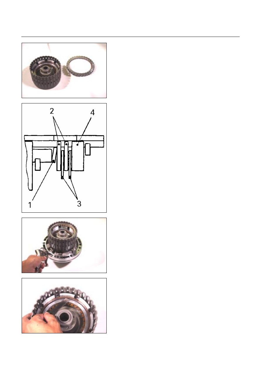
10.Dish plate, drive plates, driven plates, and retaining

plate 

Install the reverse clutch dish plate (1) the 2 driven plates 

(2), the 2 drive plates (3),  and retaining plate (4). 


248L300003 


11.Snap ring 

Install the snap ring. 


22R&H35 


  Install the reverse and high clutch drum to the oil pump 

assembly. 

  Force compressed air (392 kPa/4.0 kg/cm

2

) through the

oil pump oil passages to check high clutch operation. 

If the clutch does not operate, the seal ring may be 

damaged or the parts may have been installed in the 

wrong order. 


23CLEAR02 


 Measure the

clearance between the high clutch 

retaining plate and the snap ring. 

If the clearance is outside the specified range, replace 

the existing retaining plate with a new plate of the 

proper size (thickness). 

High clutch retaining plate and snap ring clearance 

(A): 1.2~1.6 mm (0.047~0.063 in) 

Available high clutch retaining plate thicknesses 

4.6 mm (0.181 in) 

4.8 mm (0.189 in) 

7A4-40  UNIT REPAIR (JR405E) 


248L300004 


5.0 mm (0.197 in) 

5.2 mm (0.205 in) 

5.4 mm (0.213 in) 


24R&H34 


  Force compressed air (392 kPa/4.0 kg/cm

2

) through the 

oil pump oil passages to check reverse clutch operation.

If the clutch does not operate, the seal ring may be 

damaged or the parts may have been installed  in the 

wrong order. 


25CLEAR04 


  Measure the clearance between the reverse clutch 

retaining plate and the snap ring. 

If the clearance is outside the specified range, replace 

the existing retaining plate with a new plate of the

proper size (thickness). 

Reverse clutch retaining plate and snap ring

clearance (B): 

0.6~0.9 mm (0.024~0.035 in) 

Available reverse clutch retaining plate thicknesses 

4.8 mm (0.189 in) 

5.0 mm (0.197 in) 

5.2 mm (0.205 in) 

5.4 mm (0.213 in) 


UNIT REPAIR (JR405E)  7A4-41 


CARRIER AND LOW CLUTCH 

ASSEMBLY 


01C&L12 

Legend 


1. Snap ring 


2. Front carrier 


3. Bearing (with bearing race) 


4. Rear sun gear 

 5. 

Bearing 

 6. 

Rear 

carrier 


7. Bearing race 

 8. 

Bearing 


9. Rear internal gear 

  10. Bearing race 
  11. Snap ring 
  12. Retaining plate 
  13. Drive plates (7, low clutch) 
  14. Driven plates (6, low clutch) 


  15. Driven plate (1, 2 mm thick, low clutch)
  16. Dish plate 
 17. 

Snap 

ring 

 18. 

Cancel 

cover 

 19. 

Return 

spring 

  20. Low clutch piston 
  21. Seal ring (small) 
  22. Seal ring (large) 
  23. Low clutch drum 
 24. 

Bearing 

 25. 

Snap 

ring 

  26. Low one-way clutch 
  27. Side plate 
 28. 

Snap 

ring 


7A4-42  UNIT REPAIR (JR405E) 


02C&L-SUB03 


Disassembly steps 

1. Snap ring 

Remove the snap ring from the low clutch drum. 


03C&L-SUB05 


2. Front carrier 

Remove the front carrier from the low clutch assembly. 


04C&L-SUB06 


3.  Bearing (with bearing race) 

4. Rear sun gear 

5. Bearing 

6. Rear carrier 

7. Bearing race 

8. Bearing 

9. Rear internal gear 

10.Bearing race 

Remove the bearing (with bearing race), the rear sun gear, 

the bearing, the rear carrier, the bearing race, the bearing, 

and rear internal gear. 


05C&L-SUB07 


Content   ..  1791  1792  1793  1794   ..