Content .. 1660 1661 1662 1663 ..
Isuzu D-Max / Isuzu Rodeo (TFR/TFS). Manual - part 1662
1-34 HEATING AND AIR CONDITIONING
DISASSEMBLY
Disassembly Steps
▲
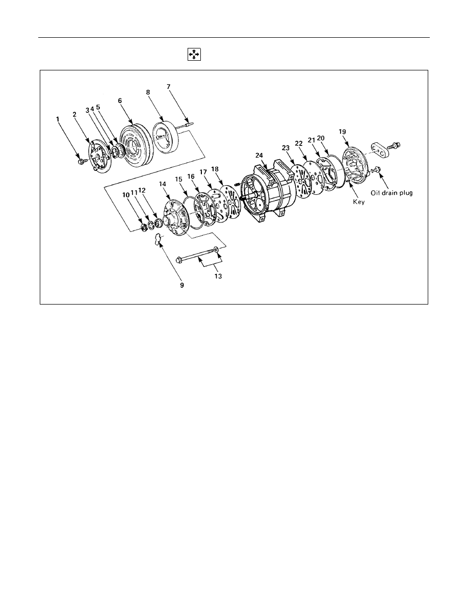
1. Drive plate bolt
▲
2. Drive plate
3. Shim(s)
4. Snap ring
▲
5. Cover (If so equipped)
▲
6. Pulley assembly
7. Lead wire connector
▲
8. Field coil
9. Felt (If so equipped)
▲
10. Shaft seal cover (If so equipped)
▲
11. Snap ring
▲
12. Shaft seal assembly
13. Through bolt with gasket
▲
14. Front cylinder head
▲
15. O-ring
16. Gasket
17. Front valve plate
▲
18. Front suction valve
▲
19. Rear cylinder head
▲
20. O-ring
21. Gasket
22. Rear valve plate
23. Rear suction valve
▲
24. Cylinder and shaft assembly