Isuzu D-Max / Isuzu Rodeo (TFR/TFS). Manual - part 1546


  Index      Ford     Isuzu D-Max / Isuzu Rodeo TFR/TFS series - service repair manual 1997-2003 year


Search            


Content   ..  1544  1545  1546  1547   ..


Isuzu D-Max / Isuzu Rodeo (TFR/TFS). Manual - part 1546


8-284  ELECTRICAL-BODY AND CHASSIS

  INSPECTION AND REPAIR

Harness side

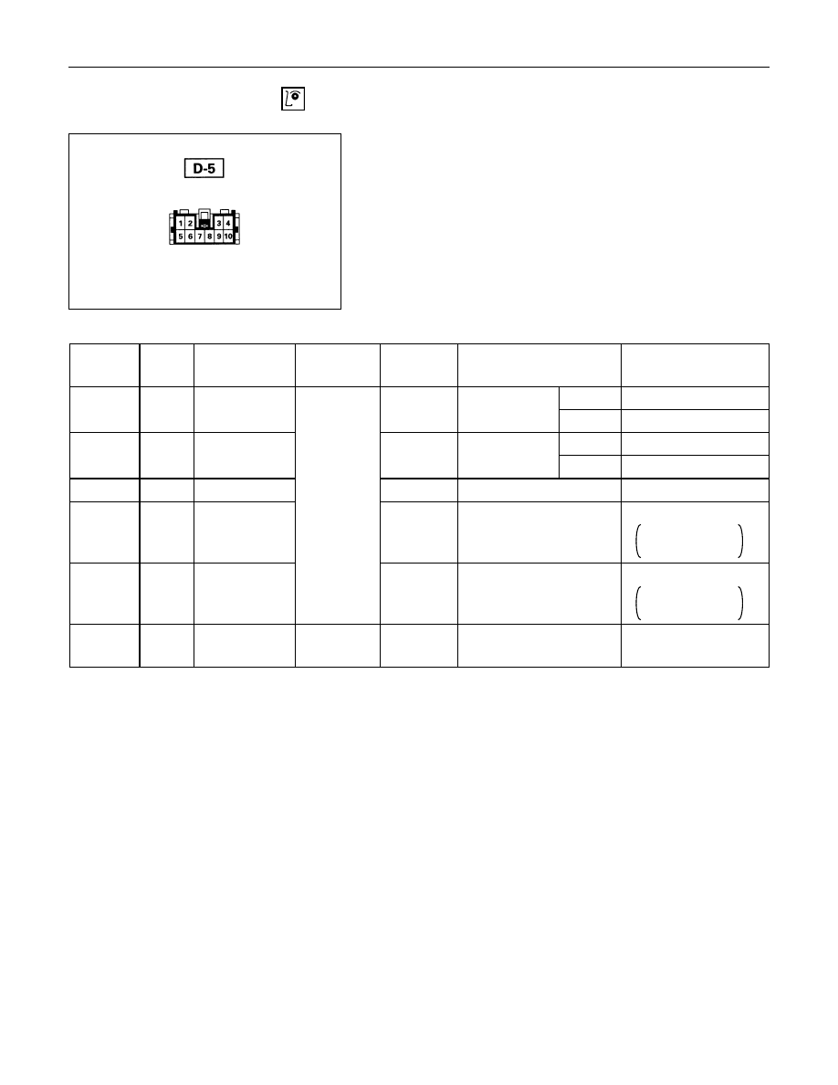
Driver Seat Side Power Window & Door Lock
Switch

1. Harness Side Connector Circuit

Check  voltage  and  continuity  between  the  switch  harness

side connector terminals as shown in the following table.

Terminal

No.

Wire

color

Connecting to

Check item

Connecting

terminal

Check condition

Standard

Door lock SW

Driver seat

Lock

Continuity

(Lock)

side door

Unlock

No continuity

Door lock SW

Driver seat

Lock

No continuity

(Unlock)

side door

Unlock

Continuity

5

B

Ground

Continuity

5-Ground

-

Continuity

6

L/Y

Door lock

actuator (Lock)

(Resistance)

6-8

-

Continuity

There is some

resistance

8

Y/G

Door lock

actuator

(Unlock)

8-6

-

Continuity

There is some

resistance

9

LG/W

Fuse

CB-15 (20A)

Voltage

9- Ground

-

Battery voltage

(Approx. 12V)

3-Ground

R/W

3

4-Ground

LG/R

4

ELECTRICAL-BODY AND CHASSIS  8-285

Switch side

2. Switch Side Connector Circuit

Remove  the  switch  connector,  and  check  continuity  and

voltage between the switch connector terminals.

(Connect the (+) terminal of the  battery  to  9 

D-5

  and  the

(-) terminal to 5 

D-5

.)

D-5

 - 6 

D-5

.................. Continuity

D-5

 - 8 

D-5

.................. Continuity

(Then, ground 3 

D-5

.)

D-5

........... Current flow for approx. 1 second

(Disconnect the ground of 3 

D-5

, and ground 4 

D-5

.)

D-5

........... Current flow for approx. 1 second

Harness side

3. Door Lock Operation Test

After  confirming  that  there  is  continuity  between  the  switch

harness  side  connector  terminals  6 

D-5

  and  8 

D-5

,

apply the battery voltage to each of the terminals to conduct

the operation test.

When  the  door  lock  will  not  operate,  check  the  door  lock

actuator for any trouble.

Connecting terminals

8 (Y/G)

6 (L/Y)

+

-

Unlock

-

+

Lock

Operation

8-286  ELECTRICAL-BODY AND CHASSIS

Switch side

Driver’s Side Door Lock Switch

1. Switch Side Connector Circuit

Check continuity between the switch connector terminals

Terminal No.

SW position

1

2

3

Lock

Unlock

Actuator side

Front Passenger’s Side Door Lock Actuator

1. Actuator Side Connector Circuit

Apply the battery voltage to the actuator connector terminals

to check the operation.

When the door lock actuator is checked on the vehicle and

there is no continuity, and when the door lock actuator itself

is  checked  and  no  trouble  is  found,  check  the  circuit

between  the  door  lock  actuator  and  the  driver  seat  side

power window & door lock switch for any failure.

Connecting terminals

2

4

+

-

Lock

-

+

Unlock

Operation

Actuator side

Rear Door Lock Actuator -LH & RH

1. Actuator Side Connector Circuit

Apply the battery voltage to the actuator connector terminals

to check the operation.

When the door lock actuator is checked on the vehicle and

there is no continuity, and when the door lock actuator itself

is  checked  and  no  trouble  is  found,  check  the  circuit

between  the  door  lock  actuator  and  the  driver  seat  side

power window & door lock switch for any failure.

Connecting terminals

1

3

-

+

Lock

+

-

Unlock

Operation

ELECTRICAL-BODY AND CHASSIS  8-287

POWER WINDOW

PARTS LOCATION (LHD)


Content   ..  1544  1545  1546  1547   ..