Isuzu D-Max / Isuzu Rodeo (TFR/TFS). Manual - part 145
6E–184
4JH1 ENGINE DRIVEABILITY AND EMISSIONS
10
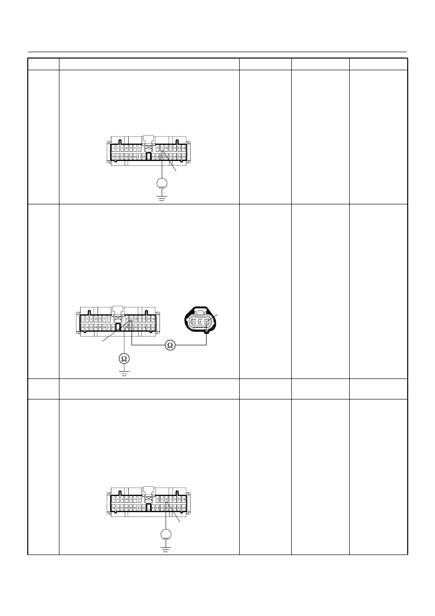
Using the DVM and check the VSS signal circuit.
1. Ignition “On”, engine “Off”.
2. Disconnect the meter connector.
3. Check the circuit for short to power supply circuit.
Was the DVM indicated specified value?
Less than 1V
Go to Step 11
Repair faulty
harness and
verify repair
11
Using the DVM and check the VSS signal circuit.
1. Ignition “Off”, engine “Off”.
2. Disconnect the VSS connector and meter
connector.
3. Check the circuit for open or short to ground
circuit.
If a open or short to ground circuit is found, repair the
faulty harness and verify repair.
Is the action complete?
—
Verify repair
—
12
Replace the speed meter.
Is the action complete?
—
Verify repair
—
13
Using the DVM and check the VSS signal circuit.
1. Ignition “Off”, engine “Off”.
2. Disconnect the meter connector and ECM
connector.
3. Ignition “On”.
4. Check the circuit for short to power supply circuit.
Was the DVM indicated specified value?
Less than 1V
Go to Step 14
Repair faulty
harness and
verify repair
Step
Action
Value(s)
Yes
No
9
V
B-24
3
9
E-44
B-24
10
V
B-24