Isuzu D-Max / Isuzu Rodeo (TFR/TFS). Manual - part 143


  Index      Ford     Isuzu D-Max / Isuzu Rodeo TFR/TFS series - service repair manual 1997-2003 year


Search            


Content   ..  141  142  143  144   ..


Isuzu D-Max / Isuzu Rodeo (TFR/TFS). Manual - part 143


6E–176

4JH1 ENGINE DRIVEABILITY AND EMISSIONS

8

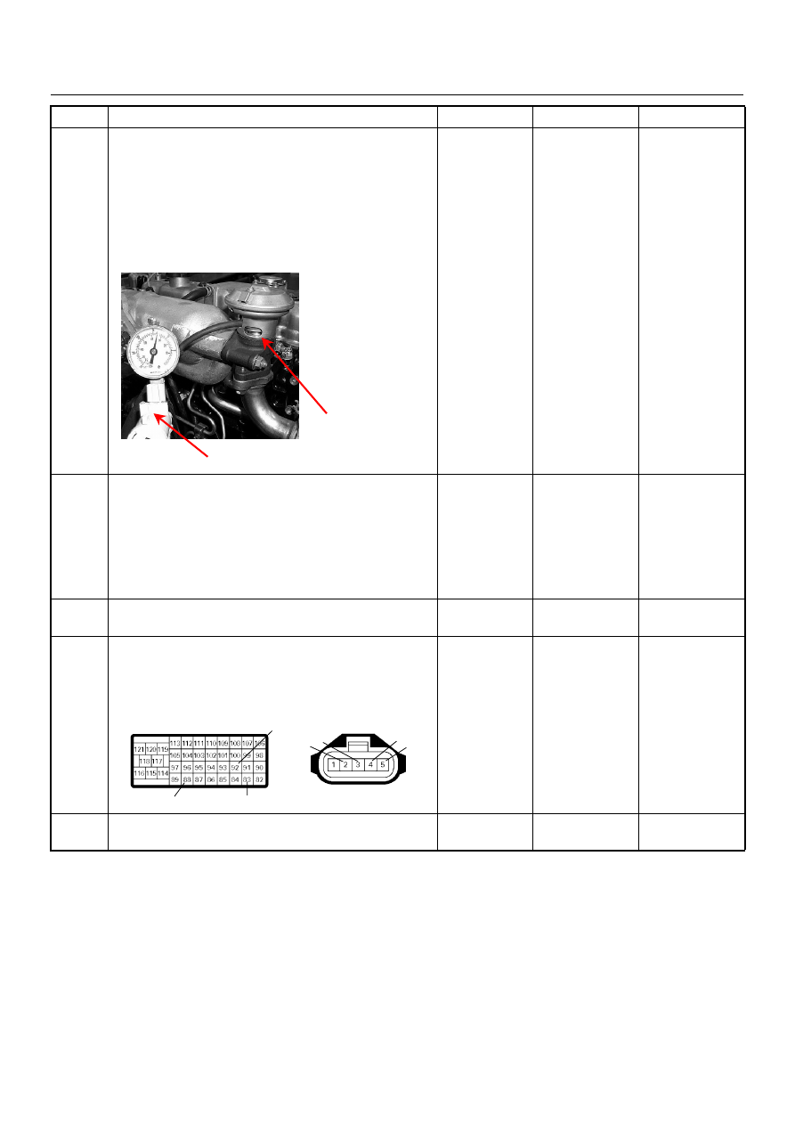
Using the vacuum pump and check the EGR valve
operation for the following condition through the small
window. 

• Restrict shaft movement. Check for objects sticking

the shaft, broken diaphragm or excessive carbon
deposit.

If a problem is found, repair as necessary. 
Was a problem found? 

Verify repair or 

Go to Step 10

Go to Step 9

9

Inspect the EGR valve.

1. Remove the EGR valve from the engine. 

2. Inspect the EGR valve whether pintle valve is

stuck or damaged. 

If excessive carbon deposit is found, clean up the
EGR valve and inspect damage of the pintle and seat. 
Was the problem found?

Verify repair or 

Go to Step 10

Go to Step 11

10

Replace the EGR valve. 
Is the action complete?

Verify repair

-

11

Check for poor/faulty connection at the MAF sensor or
ECM connector. If a poor/faulty connection is found,
repair as necessary. 
Was the problem found?

Verify repair

Go to Step 12

12

Visually check the MAF sensor. 
Was the problem found? 

Go to Step 14

Go to Step 13

Step

Action

Value(s)

Yes

No

Vacuum Pump

Small Window

92

88

83

2 3

4

5

C-116

C-57(B)

4JH1 ENGINE DRIVEABILITY AND EMISSIONS

6E–177

13

Using the DVM and check the MAF sensor signal
circuit.

1. Ignition “On”, engine “Off”. 

2. Disconnect the MAF sensor connector. 

3. Check the circuit for short to power supply circuit. 

Was the DVM indicated specified value?

Less than 1V

Go to Step 16

Repair faulty 
harness and 

verify repair

14

Substitute a known good MAF & IAT sensor assembly
and recheck. 
Was the problem solved?

Go to Step 15

Go to Step 16

15

Replace the MAF & IAT sensor assembly. 
Is the action complete?

Verify repair

16

Is the ECM programmed with the latest software
release? 
If not, download the latest software to the ECM using
the “SPS (Service Programming System)”. 
Was the problem solved?

Verify repair

Go to Step 17

17

Replace the ECM. 
Is the action complete? 
IMPORTANT: The replacement ECM must be
programmed. Refer to section of the Service
Programming System (SPS) in this manual. 
Following ECM programming, the immobiliser system
(if equipped) must be linked to the ECM. Refer to
section 11 “Immobiliser System-ECM replacement” for
the ECM/Immobiliser linking procedure.

Verify repair

Step

Action

Value(s)

Yes

No

5

V

C-116

6E–178

4JH1 ENGINE DRIVEABILITY AND EMISSIONS

Diagnostic Trouble Code (DTC) P0400 (Symptom Code 8) (Flash Code 32) 

Exhaust Gas Recirculation Circuit Short to Battery

Step

Action

Value(s)

Yes

No

1

Was  the  “On-Board Diagnostic (OBD) System Check”
performed?

Go to Step 2

Go to On Board 

Diagnostic 

(OBD) System 

Check

2

1. Connect the Tech 2. 

2. Review and record the failure information. 

3. Select “F0: Read DTC Infor As Stored By ECU” in

“F0: Diagnostic Trouble Codes”. 

Is the DTC P0400 (Symptom Code 8) stored as
“Present Failure”?

Go to Step 3

Refer to 

Diagnostic Aids 

and Go to Step 

3

3

1. Using the Tech 2, ignition “On” and engine “Off”. 

2. Select  “F1: Clear DTC Information” in “F0:

Diagnostic Trouble Codes” with the Tech 2 and
clear the DTC information. 

3. Operate the vehicle and monitor the “F0: Read

DTC Infor As Stored By ECU” in the “F0:
Diagnostic Trouble Codes”. 

Was the DTC P0400 (Symptom Code 8) stored in this
ignition cycle?

Go to Step 4

Refer to 

Diagnostic Aids

4

Check for poor/faulty connection at the EGR EVRV or
ECM connector. If a poor/faulty connection is found,
repair as necessary. 
Was the problem found?

Verify repair

Go to Step 5

5

Using the DVM and check the EGR EVRV.

1. Ignition “Off”,  engine “Off”. 

2. Disconnect the EGR EVRV connector. 

3. Measure the resistance of EGR EVRV solenoid

coil. 

Does the tester indicate standard resistance?   

Approximately 

14

Ω at 20°C

Go  to  Step 6

Go to Step 8

97

1

2

C-115

C-57

1

2

EGR EVRV

1

2

4JH1 ENGINE DRIVEABILITY AND EMISSIONS

6E–179

6

Using the DVM and check the EGR EVRV circuit. 

1. Ignition “Off”, engine “Off”. 

2. Remove the EGR EVRV connector and ECM

connector. 

3. 3. Check the circuit for short to voltage circuit. 

Was the DVM indicated specified value?

No continuity

Go to Step 10

Go to Step 7

7

Repair the short to voltage circuit. 
Is the action complete?

Verify repair

8

Substitute a known good EGR EVRV and recheck. 
Was the problem solved?

Go to Step 9

Go to Step 10

9

Replace the EGR EVRV. 
Is the action complete?

Verify repair

10

Is the ECM programmed with the latest software
release? 
If not, download the latest software to the ECM using
the “SPS (Service Programming System)”. 
Was the problem solved?

Verify repair

Go to Step 11

11

Replace the ECM. 
Is the action complete? 
IMPORTANT: The replacement ECM must be
programmed. Refer to section of the Service
Programming System (SPS) in this manual. 
Following ECM programming, the immobiliser system
(if equipped) must be linked to the ECM. Refer to
section 11 “Immobiliser System-ECM replacement” for
the ECM/Immobiliser linking procedure.

Verify repair

Step

Action

Value(s)

Yes

No

1

2

C-115


Content   ..  141  142  143  144   ..