Isuzu D-Max / Isuzu Rodeo (TFR/TFS). Manual - part 144


  Index      Ford     Isuzu D-Max / Isuzu Rodeo TFR/TFS series - service repair manual 1997-2003 year


Search            


Content   ..  142  143  144  145   ..


Isuzu D-Max / Isuzu Rodeo (TFR/TFS). Manual - part 144


6E–180

4JH1 ENGINE DRIVEABILITY AND EMISSIONS

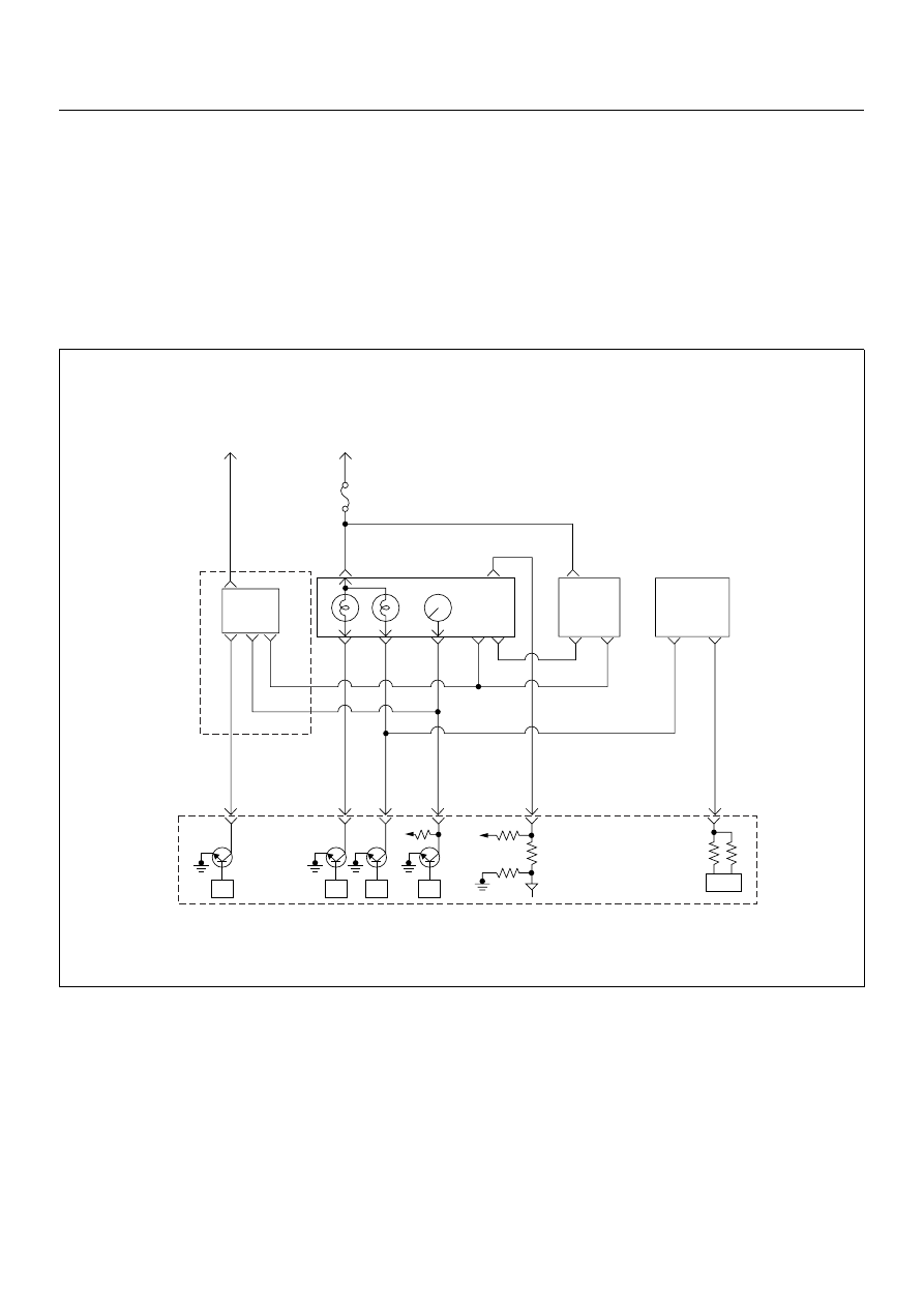
DIAGNOSTIC TROUBLE CODE (DTC) P0500 (SYMPTOM CODE 1) 

(FLASH CODE 24) VEHICLE SPEED SENSOR CIRCUIT HIGH INPUT

DIAGNOSTIC TROUBLE CODE (DTC) P0500 (SYMPTOM CODE A) 

(FLASH CODE 24) VEHICLE SPEED SENSOR INPUT SIGNAL FREQUENCY 

TOO HIGH

DIAGNOSTIC TROUBLE CODE (DTC) P0500 (SYMPTOM CODE B) 

(FLASH CODE 24) VEHICLE SPEED SENSOR INCORRECT SIGNAL

Battery
Voltage

Ignition
SW

Meter
15A

A16

A7 A10

0.5
BLK/
YEL

Batt

Batt

0.5
RED/
WHT

29

0.5
ORG/
BLU

43

0.5
BRN/
YEL

42

0.5
BLK/
RED

27

0.5
BLU/
WHT

68

0.5
WHT

35

VSS

0.85
YEL

Imnobiliser

Control Unit

7

8

0.5
BRN/
YEL

IC

4P out

0.85
YEL

Glow

Check

Engine

Tacho

Meter

A/T

A1

TCM

µP

µP

µP

µP

Engine
Control
Module
(ECM)

4JH1 ENGINE DRIVEABILITY AND EMISSIONS

6E–181

Condition for setting the DTC and action taken when the DTC sets

Circuit Description

The VSS is a magnet rotated by the transmission output
shaft. The VSS uses a hall element. It interacts with the
magnetic field treated by the rotating magnet. It outputs
pulse signal. The 12 volts operating supply from the
meter fuse.
The engine control module (ECM) calculates the vehicle
speed by VSS. 

Diagnostic Aids

An intermittent may be caused by the following:

• Poor connections.

• Misrouted harness.

• Rubbed through wire insulation.

• Broken wire inside the insulation.
Check for the following conditions:

• Poor connection at ECM-Inspect harness connectors

for backed out terminals, improper mating, broken
locks, improperly formed or damaged terminals, and
poor terminal to wire connection.

• Damaged harness-Inspect the wiring harness for

damage. If the harness appears to be OK, observe
the DTC P0500 display on the Tech2 while moving
connectors and wiring harnesses. A change in the
display will indicate the location of the fault.

Diagnostic Trouble Code (DTC) P0500 (Symptom Code 1) (Flash Code 24) 

Vehicle Speed Sensor Circuit High Input

Flash 

Code

Code

Symptom 

Code

MIL

DTC Name

DTC Setting Condition

Fail-Safe (Back Up)

24

P0500

1

ON 

at 

next 
igni-

tion 

cycle

Vehicle Speed Sensor Circuit 
High Input

Vehicle speed is more than 
200km/h.

ECM uses vehicle speed 5km/
h condition as substitute.

A

ON 

at 

next 
igni-

tion 

cycle

Vehicle Speed Sensor Input 
Signal Frequency Too High

Input signal frequency is too 
high.

ECM uses vehicle speed 5km/
h condition as substitute.

B

ON 

at 

next 
igni-

tion 

cycle

Vehicle Speed Sensor Incor-
rect Signal

1. Engine speed is more than 

3600rpm. 

2. Fuel injection quantity is 

more than 41mg/stk. 

3. Vehicle speed is below 

1.5km/h.

Fuel injection quantity is 
reduced.

Step

Action

Value(s)

Yes

No

1

Was  the  “On-Board Diagnostic (OBD) System Check”
performed?

Go to Step 2

Go to On Board 

Diagnostic 

(OBD) System 

Check

2

1. Connect the Tech 2. 

2. Review and record the failure information. 

3. Select “F0: Read DTC Infor As Stored By ECU” in

“F0: Diagnostic Trouble Codes”. 

Is the DTC P0500 (Symptom Code 1) stored as
“Present Failure”?

Go to Step 3

Refer to 

Diagnostic Aids 

and Go to Step 

3

6E–182

4JH1 ENGINE DRIVEABILITY AND EMISSIONS

3

1. Using the Tech 2, ignition “On” and engine “Off”. 

2. Select  “F1: Clear DTC Information” in “F0:

Diagnostic Trouble Codes” with the Tech 2 and
clear the DTC information. 

3. Operate the vehicle and monitor the “F0: Read

DTC Infor As Stored By ECU” in the “F0:
Diagnostic Trouble Codes”. 

Was the DTC P0500 (Symptom Code 1) stored in this
ignition cycle?

Go to Step 4

Refer to 

Diagnostic Aids 

and Go to Step 

4

4

Perform test drive and check the speed meter.
Does the speed meter indicate correct vehicle speed.

Go to Step 5

Go to Step 6

5

Perform test drive and use the Tech 2.  
Monitor the “Vehicle Speed” in the data display. 
Does the Tech 2 indicate correct vehicle speed as
same as the speed meter indication in the instrument
panel?

Go to Step 15

Go to Step 7

6

Remove the VSS from the housing case and visually
check. 
Was the problem found? 

Go to Step 8

Go to Step 7

Step

Action

Value(s)

Yes

No

4JH1 ENGINE DRIVEABILITY AND EMISSIONS

6E–183

7

Using the DVM and check the VSS signal.

1. Ignition “On”, vehicle “Run (lift up)”. 

2. Measure the VSS output voltage at sensor, TCM

(A/T 2WD), meter and ECM. 

Does the tester indicate specified value? 

If a oscilloscope is available, monitor the VSS signal at
each connector connection. Does the oscilloscope
indicate correct wave form? 

Refer to 

Diagnostic Aids 

and Go to Step 

15

Refer the table

8

Replace the VSS. 
Is the action complete?

Verify repair

9

Replace the TCM. 
Is the action complete? 
IMPORTANT: The replacement TCM must be
programmed. “SPS (Service Programming System)
is necessary.” 

Verify repair

Step

Action

Value(s)

Yes

No

Measurement Position

Voltage (V) 

(AC Range)

If No 

Good

VSS terminal 3 & GND

Approximately 6.5 

V at 20km/h

Go to 

Step 8

TCM C94 connector 10 & 
GND (A/T 2WD)

Go to 

Step 9

Meter B24 connector 9 & 
GND

Go to 

Step 10

Meter B24 connector 10 & 
GND

Go to 

Step 12

ECM C56 connector 68 & 
GND

Go to 

Step 13

Vehicle Speed Sensor Reference Wave Form

0V

Measurement Scale: 10V/div

50ms/div

Measurement Condition: Vehicle Speed 20km/h
Measurement Terminal: At Engine Control Module


Content   ..  142  143  144  145   ..