Isuzu D-Max / Isuzu Rodeo (TFR/TFS). Manual - part 1389


  Index      Ford     Isuzu D-Max / Isuzu Rodeo TFR/TFS series - service repair manual 1997-2003 year


Search            


Content   ..  1387  1388  1389  1390   ..


Isuzu D-Max / Isuzu Rodeo (TFR/TFS). Manual - part 1389


ELECTRICAL-BODY AND CHASSIS  8-121

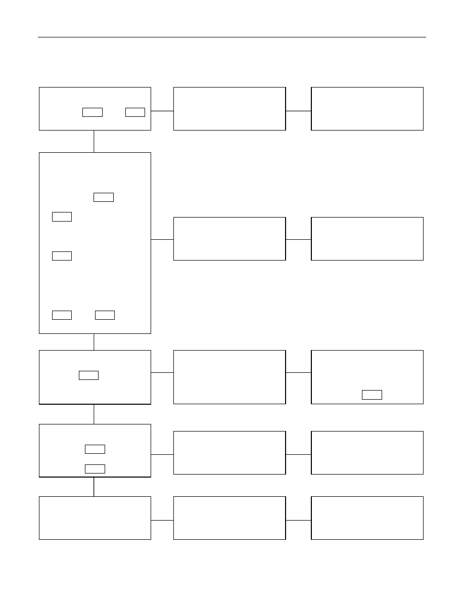
6. Auto-stop function of the wiper motor does not operate

Checkpoint

Trouble Cause

Countermeasure

Repair open circuit or

connector contact

Open circuit or poor connector

contact

NG

Repair open circuit or

connector contact

Open circuit or poor connector

contact

NG

Continuity between the
intermittent relay harness side
connector 6 

C-3

 and the

wiper motor harness side
connector 5 

C-4

Replace the intermittent relay

Relay malfunction

NG

Intermittent relay function

Wiper motor function
1. Disconnect the wiper motor

connector

2. Connect the motor

connector 2 

C-4

 to the

battery (+) terminal and 3

C-4

 to the (-) terminal,

and then change the
connection of the battery (+)
terminal to the connector 6

C-4

 while the motor

rotating at a low speed

3. Check to see if the wiper

motor stops at the auto stop
position when connecting
the connector terminals 2

C-4

 and 5 

C-4

 in this

condition

Continuity between the wiper
& washer SW. connector
terminals 5 

C-43

 and 6 

C-43

at the “OFF” position

OK

Replace the wiper motor

Wiper motor malfunction

NG

Repair an open circuit or a
poor connection of the
connectors between the fuse
No. CB-8 (20A) (RHD: CB-6
(20A) ) and 6 

C-4

Voltage between the wiper
motor harness side connector
terminal 6 

C-4

 and the

ground (Should be battery
voltage present)

Open circuit or poor connector

contact

NG

OK

OK

OK

8-122  ELECTRICAL-BODY AND CHASSIS

WASHER

1. Washer motor does not operate

Checkpoint

Trouble Cause

Countermeasure

Reinstall or replace the fuse

No. CB-8 (20A) (RHD: CB-6

(20A) )

Poor fuse contact or blown

NG

Repair or an open circuit or a
poor connection of the
connectors between 1 

C-17

and 7 

C-43

Open circuit or poor connector

contact

NG

Voltage between the washer
motor harness side connector
terminal 1 

C-17

 and the

ground when the washer
button is depressed (Should
be battery voltage present)

Repair grounding point

(

C-36

) contact

Poor grounding point contact

NG

Grounding point (

C-36

)

Replace the washer motor

Motor malfunction

NG

Washer motor function when
connecting the motor side
connector 1 

C-17

 to the

battery (+) terminal, and the
connector 2 

C-17

 to the (-)

terminal (Should the washer
motor rotate)

OK

Repair open circuit or

connector contact

Open circuit or poor connector

contact

NG

Continuity between 2 

C-17

and 

C-36

OK

Continuity between the wiper
& washer SW. side connector
terminals 

C-43

 and 7 

C-43

when the washer button is
depressed

LHD:
Fuse No. CB-8 (20A)
RHD:
Fuse No. CB-6 (20A)

OK

Replace the wiper & washer

SW.

SW. malfunction

NG

Repair or an open circuit or a
poor connection of the
connectors between the fuse
No. CB-8 (20A) (RHD: CB-6
(20A) )and 1 

C-43

Voltage between the wiper &
washer SW. harness side
connector terminal 1 

C-43

and the ground (Should be
battery voltage preset)

Open circuit or poor connector

contact

NG

OK

OK

OK

ELECTRICAL-BODY AND CHASSIS  8-123


  REMOVAL AND INSTALLATION

WIPER AND WASHER SWITCH

Removal

Refer to the removal steps of the LIGHTING SWITCH
(COMBINATION SWITCH) in “ LIGHTING “ of this section.

Installation

Follow the removal procedure in the reverse order to install the
wiper and washer switch.

Pay close attention to the important points mentioned in the
following paragraphs.

Connector

Be absolutely sure that the wiper and washer switch connector
is securely connected.
This will prevent a poor contact and an open circuit.

8-124  ELECTRICAL-BODY AND CHASSIS

  INSPECTION AND REPAIR

Switch side

Control Switch Connections

Terminal

No.

SW position

6

3

5

4

2

1

7

Mist

Off

INT

Lo

Hi

Wash

Wiper Motor Inspection

Connector

Low Speed Inspection

1. Clamp the wiper motor in a vise.

The moving parts must be clear of the vise.

2. Connect the connector terminals to the battery.

Refer to the illustration.

3. Check the wiper motor low speed operation.


Content   ..  1387  1388  1389  1390   ..