Isuzu D-Max / Isuzu Rodeo (TFR/TFS). Manual - part 1390


  Index      Ford     Isuzu D-Max / Isuzu Rodeo TFR/TFS series - service repair manual 1997-2003 year


Search            


Content   ..  1388  1389  1390  1391   ..


Isuzu D-Max / Isuzu Rodeo (TFR/TFS). Manual - part 1390


ELECTRICAL-BODY AND CHASSIS  8-125

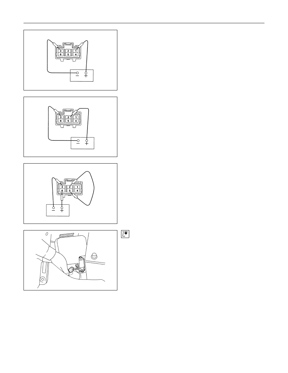
High Speed Inspection

1. Clamp the wiper motor in a vise.

The moving parts must be clear of the vise.

2. Connect the connector terminals to the battery.

Refer to the illustration.

3. Check the wiper motor high speed operation.

Auto-Stop Inspection

1. Clamp the wiper motor in a vise.

The moving parts must be clear of the vise.

2. Connect the connector terminals to the battery.

Refer to the illustration.

3. Check the wiper motor low speed operation.

4. Disconnect the positive battery terminal.

This will stop the motor.

5. Connect  the  connector  terminals  No.  2  and  No.  5  with  a

lead wire.

Refer to the illustration.

6. Reconnect  the  positive  battery  terminal  to  connector

terminal No. 6.

This will restart the motor.

Refer to the illustration.

7. Check the auto-stop operation.

Washer Motor Inspection

1. Fill the washer tank with washing solution.

2. Disconnect the motor connector.

3. Apply battery voltage to the washer motor connector.

4. Check the washer motor operation.

8-126  ELECTRICAL-BODY AND CHASSIS

WIPER MOTOR AND LINKAGE

Removal

1. Disconnect the wiper motor connector 

1

.

2. Remove the wiper motor bracket screws 

2

.

3. Disconnect  the  wiper  motor  from  the  wiper  linkage  at  the

crank arm 

3

.

4. Disconnect the wiper arm nut cap 

4

.

5. Remove the wiper arm nut 

5

.

6. Remove the wiper arm with blade.

7. Remove the vent cowl cover 

6

.

ELECTRICAL-BODY AND CHASSIS  8-127

8. Remove the wiper linkage 

7

 from the access hole.

Installation

Follow the removal procedure in the reverse order to install the
wiper motor and linkage.
Pay close attention to the important points mentioned in the
following paragraphs.

Wiper Linkage

Take care not to scratch the painted surfaces of the body when
installing the wiper linkage to the body.
In case crank arm of wiper motor is removed, confirm the
position of auto stop prior to reinstall the crank arm to the wiper
motor.
Crank Arm Nut Torque

N

⋅m (kgf⋅m/lb⋅ft)

13.7 

± 2.0 (1.4 ± 0.2/10 ± 1.4)

Wiper Blade Position

Confirm the auto stop position of wiper motor prior to the
installation of the wiper blade and arm.
The distance between the vent cowl cover rubber seal 

1

 and

the wiper blade edge 

2

 is about 45 mm(1.8 in).

Wiper Arm Nut

Tighten the wiper arm nut to the specified torque.
Wiper Arm Nut Torque

N

⋅m (kgf⋅m/lb⋅ft)

13.7 

± 2.0 (1.4 ± 0.2/10 ± 1.4)

8-128  ELECTRICAL-BODY AND CHASSIS

Windshield Washer Spray

Be sure that the engine hood 

1

 is completely closed before

checking the windshield washer spray adjustment.
Windshield Washer Spray Position

mm(in)

A

Approximately 300 (11.8)

Connector

Be absolutely sure that the wiper motor connector is securely
connected.
This will prevent a poor contact and an open circuit.

Note:
Windshield wiper arm and blade assembly configurations
are different for the right-hand and left-hand side of the
vehicle.
Be careful not to confuse the right-hand and left-hand side
assemblies.

WASHER TANK MOTOR

Removal

1. Remove the washer tank bolts.

2. Disconnect the connector 

1

.

3. Disconnect the water hose 

2

.

4. Remove the washer tank motor 

3

.


Content   ..  1388  1389  1390  1391   ..