Isuzu D-Max / Isuzu Rodeo (TFR/TFS). Manual - part 1343


  Index      Ford     Isuzu D-Max / Isuzu Rodeo TFR/TFS series - service repair manual 1997-2003 year


Search            


Content   ..  1341  1342  1343  1344   ..


Isuzu D-Max / Isuzu Rodeo (TFR/TFS). Manual - part 1343


8–292 ELECTRICAL-BODY AND CHASSIS

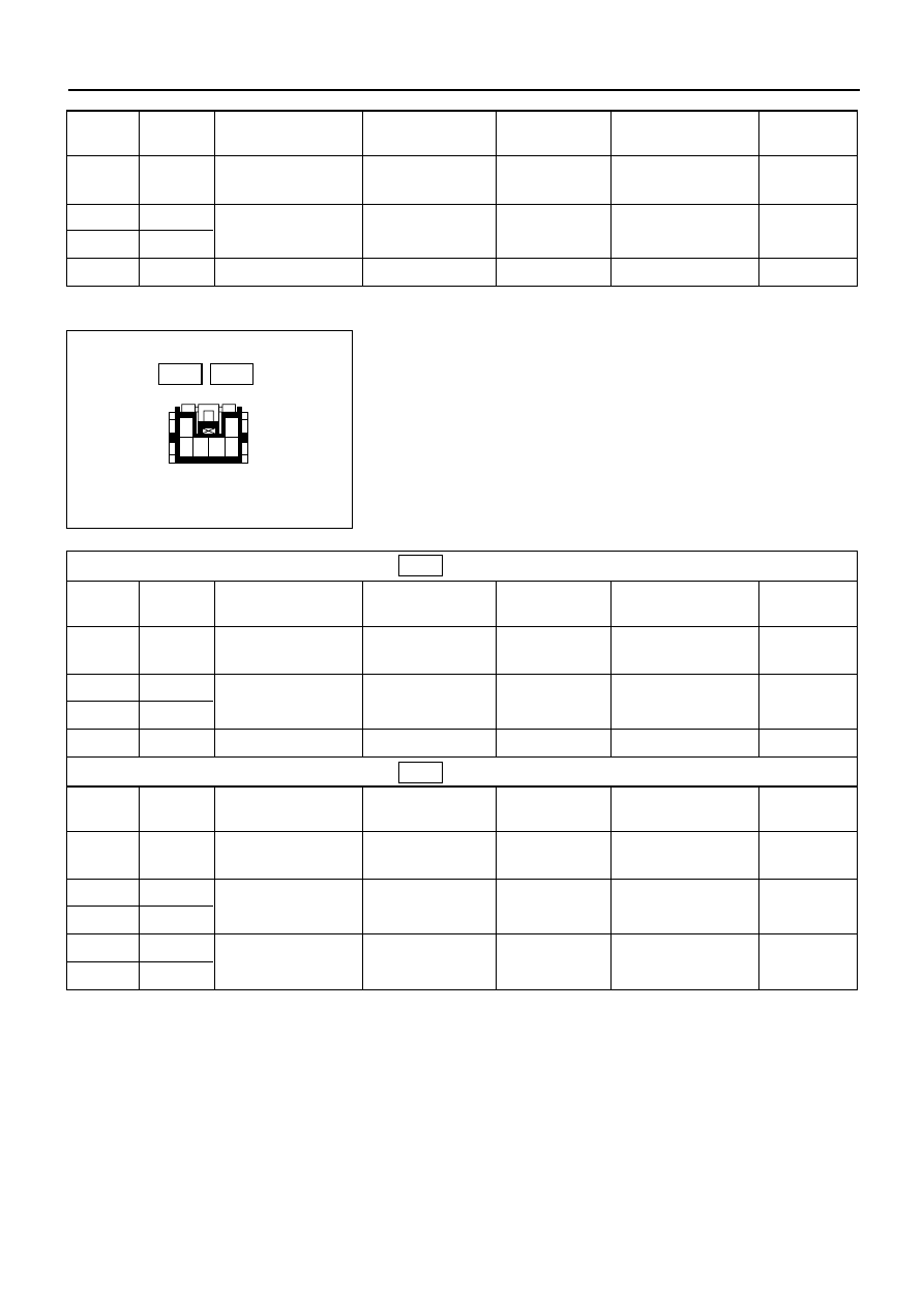
Rear Power Window Switch-LH & RH

1. Harness Side Connector Circuit

Disconnect the switch connector, and check voltage
and continuity between the harness side connector
terminals as shown in the following tables.

1

3 4 5 6

2

Terminal

Wire

Connecting to

Check item

Connecting

Check condition

Standard

No.

color

terminal

9

G/R

Power window

Voltage

9-Ground

Starter SW “ON”

Approx.

relay

12V

6

L/R

Power window

Continuity

6 – 10

Continuity

10

L/W

motor

5

B

Ground

Continuity

5-Ground

Continuity

(RR–LH)

Terminal

Wire

Connecting to

Check item

Connecting

Check condition

Standard

No.

color

terminal

4

G/R

Power window

Voltage

4-Ground

Starter SW “ON”

Approx.

relay

12V

5

L/R

Power window

Continuity

5 – 6

Continuity

6

BR/W

motor

3

B

Ground

Continuity

3-Ground

Continuity

(RR–RH)

Terminal

Wire

Connecting to

Check item

Connecting

Check condition

Standard

No.

color

terminal

4

G/R

Power window

Voltage

4-Ground

Starter SW “ON”

Approx.

relay

12V

5

L/R

Power window

Continuity

5 – 6

Continuity

6

BR/W

motor

3

B

Ground

Continuity

3 – 1

Continuity

1

B

Harness side

D-12

D-12

D-16

D-16

ELECTRICAL-BODY AND CHASSIS 8–293

Driver Seat Side Power Window Motor

1. Driver Seat Side Power Window & Door Lock Switch

Connector Circuit

Disconnect the switch connector, apply the battery
voltage (12V) to the harness side connector terminals
and check operation.

10

9

8

7

6

5

4

3

2

1

2. Driver Seat Side Power Window Motor Connector

Circuit

Disconnect the switch connector, apply the battery
voltage (12V) to the motor side connector terminals
and check operation.

1

2

M

DOWN

UP

825RV092

Harness side

Motor side

D-5

D-1

Connecting terminals

Operation direction

1 (L/R)

10 (L/W)

+

DOWN

+

UP

Connecting terminals

Operation direction

1

2

+

DOWN

+

UP

8–294 ELECTRICAL-BODY AND CHASSIS

Front Passenger’s Power Window Motor

1. Front Passenger’s Power Window Switch & Door

Lock Switch Connector Circuit

Disconnect the motor connector, apply the battery
voltage (12V) to the harness side connector terminals
and check operation.

10

9

8

7

6

5

4

3

2

1

2. Front Passenger’s Power Window Motor Connector

Circuit

Disconnect the switch connector, apply the battery
voltage (12V) to the motor side connector terminals
and check operation.

1

2

M

DOWN

UP

825RV092

Harness side

Motor side

D-10

D-6

Connecting terminals

Operation direction

6 (L/R)

10 (L/W)

+

DOWN

+

UP

Connecting terminals

Operation direction

1

2

+

DOWN

+

UP

ELECTRICAL-BODY AND CHASSIS 8–295

Rear Passenger’s Power Window Motor-LH

1. Rear Power Window Switch-LH Connector Circuit

Disconnect the motor connector, apply the battery
voltage (12V) to the harness side connector terminals
and check operation.

1

3 4 5 6

2

2. Rear Power Window Motor-LH Connector Circuit

Disconnect the switch connector, apply the battery
voltage (12V) to the motor side connector terminals
and check operation.

1

2

M

DOWN

UP

825RV092

Harness side

Motor side

D-12

D-11

Connecting terminals

Operation direction

5 (L/R)

6 (BR/W)

+

DOWN

+

UP

Connecting terminals

Operation direction

1

2

+

DOWN

+

UP


Content   ..  1341  1342  1343  1344   ..