Isuzu D-Max / Isuzu Rodeo (TFR/TFS). Manual - part 1342


  Index      Ford     Isuzu D-Max / Isuzu Rodeo TFR/TFS series - service repair manual 1997-2003 year


Search            


Content   ..  1340  1341  1342  1343   ..


Isuzu D-Max / Isuzu Rodeo (TFR/TFS). Manual - part 1342


8–288 ELECTRICAL-BODY AND CHASSIS

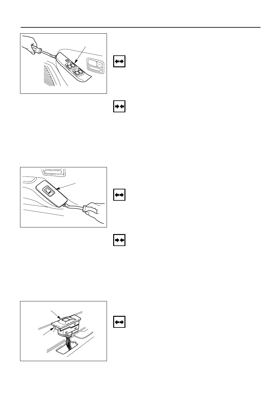
DRIVER SEAT SIDE POWER WINDOW & DOOR
LOCK SWITCH 
(4 DOORS MODEL)

Removal

1. Remove the switch by pushing the spring with the tip

of a screwdriver.

2. Disconnect the connector.

Switch

825RV098

Installation

To install, follow the removal steps in the reverse order.

FRONT PASSENGER’S POWER WINDOW &
DOOR LOCK SWITCH
(4 DOORS MODEL)

Removal

1. Remove the switch by pushing the spring with the tip

of a screwdriver.

2. Disconnect the connector.

Switch

825RV086

REAR POWER WINDOW & DOOR LOCK
SWITCH-LH & RH

Removal

1. Remove the switch by pushing the spring with the tip

of a screwdriver.

2. Disconnect the connector.

Switch

Spring

825RV096

Installation

To install, follow the removal steps in the reverse order.

This illustration is based on RHD

This illustration is based on RHD

ELECTRICAL-BODY AND CHASSIS 8–289

Installation

To install, follow the removal steps in the reverse order.

DRIVER SEAT SIDE POWER WINDOW MOTOR

Removal

1. Window Regulator ASM

Refer to the removal steps of the WINDOW
REGULATOR/POWER WINDOW MOTOR in Section
10 “BODY”.

2. Power Window Motor

Loosen the fixing bolts to remove the power
window motor from the regulator.

2.Power window motor

1.Window 
   regulator
   ASM

825RV091

Installation

To install, follow the removal steps in the reverse order.

FRONT PASSENGER’S POWER WINDOW
MOTOR

Removal

1. Window Regulator ASM

Refer to the removal steps of the WINDOW
REGULATOR/POWER WINDOW MOTOR in Section
10 “BODY”.

2. Power Window Motor

Loosen the fixing bolts to remove the power
window motor from the regulator.

2.Power window 
motor

1.Window 
   regulator
   ASM

825RV090

Installation

To install, follow the removal steps in the reverse order.

8–290 ELECTRICAL-BODY AND CHASSIS

REAR POWER WINDOW MOTOR-LH & RH

Removal and Installation

Refer to the “DRIVER SEAT SIDE POWER WINDOW
MOTOR” removal and installation steps in this section.

ELECTRICAL-BODY AND CHASSIS 8–291

Power Window Relay

Check continuity between the relay terminals.

1 - 5 . . . . . . . . . . . . . . . . . . . . No continuity

(When battery voltage is applied between 2 and 4)

1 - 5 . . . . . . . . . . . . . . . . . . . . Continuity

4

1

3

2

5

2

1

3

4

5

060RV005

Driver Seat Side Power Window & Door Lock Switch

1. Harness Side Connector Circuit

Disconnect the switch connector, and check voltage
and continuity between the harness side connector
terminals as shown in the following table.

10

9

8

7

6

5

4

3

2

1

Terminal

Wire

Connecting to

Check item

Connecting

Check condition

Standard

No.

color

terminal

2

G/R

Power window

Voltage

2-Ground

Starter SW “ON”

Approx.

relay

12V

1

L/R

Power window

Continuity

1 – 10

Continuity

10

L/W

motor

5

B

Ground

Continuity

5-Ground

Continuity

Front Passenger’s Power Window & Door Lock Switch

1. Harness Side Connector Circuit

Disconnect the switch connector, and check voltage
and continuity between the harness side connector
terminals as shown in the following table.

10

9

8

7

6

5

4

3

2

1

INSPECTION AND REPAIR

B-8

Harness side

D-5

Harness side

D-10


Content   ..  1340  1341  1342  1343   ..