Isuzu D-Max / Isuzu Rodeo (TFR/TFS). Manual - part 1340


  Index      Ford     Isuzu D-Max / Isuzu Rodeo TFR/TFS series - service repair manual 1997-2003 year


Search            


Content   ..  1338  1339  1340  1341   ..


Isuzu D-Max / Isuzu Rodeo (TFR/TFS). Manual - part 1340


8–280 ELECTRICAL-BODY AND CHASSIS

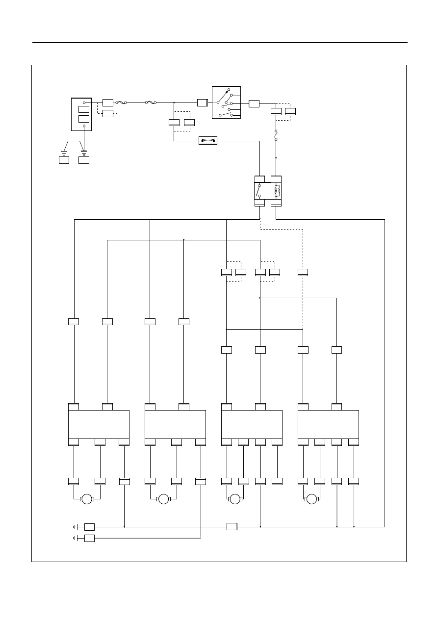
CIRCUIT DIAGRAM (LHD)

D08RW569

D - 16

4

5

D - 16

ACC

STARTER SW

IG2

ST

IG1

B2

B1

P - 1

P - 5

+

_

P - 10

30B/Y

ENG.

P - 7   

FRAME

5B/Y

15B/R

P - 2

P - 11

(6VD1)

(6VD1)

(6VD1)

(6VD1)

(6VD1)

(6VD1)

MAIN
80A OR 100A

C - 41

1

3W

8

3B/Y

C - 41

OFF

IGN.B2
40A

3

3

B-8

5

2

1

4

B-8

B-8

B-8

6

D - 16

D - 16

2

3

D - 16

1

D - 16

D - 12

4

5

D - 12

6

D - 12

D - 12

2

3

D - 12

1

D - 12

D -10

9

6

D - 10

10

D - 10

D - 10

2

5

D - 10

D - 5

2

1

D - 5

10

D - 5

D - 5

7

5

D - 5

B - 28


B - 9

BODY - LH

BODY - RH

RR POWER WINDOW
SW-RH

RR POWER WINDOW
SW-LH

FRT POWER WINDOW
AND DOOR LOCK SW-PASSENGER

FRT POWER WINDOW
AND DOOR LOCK SW-DRIVER

UP

DOWN

UP

DOWN

LOCK

UP

DOWN

UP

DOWN

2

1

1

H - 16

2

H - 16

2

1

1

H - 14

2

H - 14

2

D - 6

1

D - 6

4

2

D - 1

1

D - 1

3

2L/R

2L/W

2B

2L/R

2L/W

2B

2L/R

2BR/W

0.5B

2B

2L/R

2BR/W

0.5B

2B

2B

2B

2B

0.5B

2B

FRT POWER WINDOW
MOTOR-DRIVER

FRT POWER WINDOW
MOTOR-PASSENGER

RR POWER WINDOW
MOTOR-LH

RR POWER WINDOW
MOTOR-RH

H - 16

3

H -16

8

H - 14

3

H - 14

8

3

2

1

2

1

2

2G/R

0.5R/Y

2G/R

0.5R/Y

2G/R

0.5R/Y

2G/R

2G/R

0.5R/Y

2G/R

2G/R

0.5R/Y

0.5R/Y

2G/R

2G/R

0.5R/Y

0

.5R/Y

0.5R/Y

2G/R

0.5R/Y

0.5W

0.85W

3W

2G/W

CB-11
15A BACK UP, TURN

CIRCUIT BREAKER 30A

0.5B

M

M

M

M

RELAY;
POWER WINDOW

2B

H - 10

H - 10

H - 13

H - 13

H - 9

H - 9

10

H - 34

H - 13

H - 10

D - 15

D - 15

H-7

H-28

3W

6

3B/Y

D - 11

D - 11

H-34

1

H-7

6

H-28

2

H - 34

1

H - 34

TROUBLE SHOOTING

ELECTRICAL-BODY AND CHASSIS 8–281

CIRCUIT DIAGRAM (RHD)

D08RW570

D - 16

4

5

D - 16

ACC

STARTER SW

IG2

ST

IG1

B2

B1

P - 1

P - 5

+

_

P - 10

30B/Y

ENG.

P - 7   

FRAME

5B/Y

15B/R

P - 2

P - 11

(6VD1)

MAIN
80A OR 100A

C - 41

1

3W

8

3B/Y

C - 41

OFF

IGN.B2
40A

5

B-8

5

2

1

4

B-8

B-8

B-8

6

D - 16

D - 16

2

3

D - 16

1

D - 16

D - 12

4

5

D - 12

6

D - 12

D - 12

2

3

D - 12

1

D - 12

D -10

9

6

D - 10

10

D - 10

D - 10

2

5

D - 10

D - 5

2

1

D - 5

10

D - 5

D - 5

7

5

D - 5

B - 28


B - 9

BODY - RH

BODY - LH

RR POWER WINDOW
SW-RH

RR POWER WINDOW
SW-LH

FRT POWER WINDOW
AND DOOR LOCK SW-PASSENGER

FRT POWER WINDOW
AND DOOR LOCK SW-DRIVER

UP

DOWN

UP

DOWN

LOCK

UP

DOWN

UP

DOWN

2

1

1

H - 16

2

H - 16

2

1

1

H - 14

2

H - 14

2

D - 6

1

D - 6

4

2

D - 1

1

D - 1

3

2L/R

2L/W

2B

2L/R

2L/W

2B

2L/R

2BR/W

0.5B

2B

2L/R

2BR/W

0.5B

2B

2B

2B

2B

2B

0.5B

2B

FRT POWER WINDOW
MOTOR-DRIVER

FRT POWER WINDOW
MOTOR-PASSENGER

RR POWER WINDOW
MOTOR-LH

RR POWER WINDOW
MOTOR-RH

H - 16

3

H -16

8

H - 14

3

H - 14

8

3

2

1

2

1

2

2G/R

0.5R/Y

2G/R

0.5R/Y

2G/R

0.5R/Y

2G/R

2G/R

0.5R/Y

2G/R

2G/R

0.5R/Y

0.5R/Y

2G/R

2G/R

0.5R/Y

0.5R/Y

0.5R/Y

2G/R

0.5R/Y

0.5W

0.85W

3W

2G/W

CB-11
15A BACK UP, TURN

CIRCUIT BREAKER 30A

0.5B

M

M

M

M

RELAY;
POWER WINDOW

2B

H - 10

H - 10

H - 13

H - 13

H - 9

H - 9

2

10

H - 34

(6VD1)

(6VD1)

(6VD1)

H - 34

H - 13

H - 10

D - 15

D - 15

H-7

3W

6

3B/Y

D - 11

D - 11

H - 34

1

H-7

1

H - 34

8–282 ELECTRICAL-BODY AND CHASSIS

Check Points

Trouble Mode

Fuse

Circuit

Relay;

CB-11 Breaker

Power

Cable

(15A)

(30A)

Window

Driver’s Passenger’s

RR-LH RR-RH

Driver’s Passenger’s

RR-LH RR-RH

Harness

Side

Side

Side

Side

All windows will not
operate

Lock SW does not function

Driver’s Window:

Window does not operate

One-touch operation for
“DOWN” movement will
not operate

Window operates in only
one direction

Front window on
passenger seat side:

Window does not operate

Window does not operate
when operating the
driver’s SW

Window does not operate
when operating the
passenger’s SW

Window does operate in
only one direction when
operating the driver’s SW

Window does operate in
only one direction when
operating the passenger’s
seat side SW

Rear window on left (or
right) side:

Window on left (or right)
side does not operate

Window does not operate
when operating the
driver’s SW

Window does operate in
only one direction when
operating the driver’s SW

Window does operate in
only one direction when
operating the RR-LH (or
RH) side SW

Power Window &
Door Lock Switch

Power Window
Switch

Power Window Motor

TROUBLE SHOOTING

QUICK CHART FOR CHECK POINTS

ELECTRICAL-BODY AND CHASSIS 8–283

1.

All windows do not operate

Checkpoint

Trouble Cause

Countermeasure

Poor fuse contact or blown

Reinstall or replace the fuse
No. CB-11(15A)

Fuse CB-11 (15A, Fuse box)

Circuit breaker malfunction

Replace the circuit breaker
(30A)

Circuit breaker (30A, Fuse
box) function

Poor grounding point
contact

Repair grounding points 
( B-9 and B-28 ) 

contact

Grounding points ( B-9
and B-28 )

OK

OK

OK

NG

NG

NG

Power window relay
malfunction

Replace the power window
relay

Power window relay
function

NG

OK

Open circuit or poor
connector contact

Repair an open circuit or a
poor connection of the
connectors between 3  H-7
(RHD: 5  H-7  ) and 5  B-8

Voltage between the power
window relay harness side
connector terminal 5  B-8
and the ground (Should be
battery voltage present)

NG

OK

Open circuit or poor
connector contact

Repair an open circuit or a
poor connection of the
connectors between 
1 B-8 and 

2 D-5

Voltage between 2  D-5
and the ground (Should be
battery voltage present)

NG

OK

Open circuit or poor
connector contact

Repair an open circuit or a
poor connection of the
connectors between 5  D-5
and  B-28 , or 4  B-8 and

B-28

Voltage between  B-28
and the ground

NG

Continued on the next page


Content   ..  1338  1339  1340  1341   ..